Electrochemical systems and methods of operating same

Active Publication Date: 2012-11-22
RAMOT AT TEL AVIV UNIV LTD
View PDF2 Cites 48 Cited by
  • Summary
  • Abstract
  • Description
  • Claims
  • Application Information

AI Technical Summary

Benefits of technology

[0011]This disclosure generally relates to electrochemical systems, e.g., a combination of an electrical energy source and an electrical energy storage system having a regenerative fuel cell system, that exhibit operational stability in harsh environments, e.g., both charging and discharging reactions in a regenerative fuel cell in the presence of an acid or a mixture of acids, or a halogen ion or a mixture of halogen ions. This disclosure also relates to electrochemical systems that are capable of conducting both hydrogen evolution reactions (HERs) and hydrogen oxidation reactions (HORs) in the same system. This disclosure further relates to electrochemical systems having low cost, fast response time, and acceptable life and performance.

Problems solved by technology

For regenerative fuel cell such as hydrogen / bromine fuel cells, an important factor limiting its cycle life and efficiency is the degradation of the operating fuel cell materials.
These materials are exposed to a highly corrosive bromine electrolyte for long periods of time at elevated temperature.
The world is facing a major energy and clean air challenges.
Unfortunately, the current state of the art of conventional renewable energy sources, e.g., wind turbine generators and solar energy, and energy storage systems, and the integration of renewable energy sources and energy storage systems, have not been fully developed from a standpoint of efficiency and cost effectiveness to meet the challenges.
Current energy systems typically lack a commercially viable nighttime off-peak energy storage systems.
Solid oxide fuel cell systems that generate electricity for utility use are generally designed to use natural gas or methane as the base fuel for hydrogen, thus contributing to air quality degradation.
Integrated electrolysis systems have not been fully developed to use low priced off-peak produced renewable energy for producing hydrogen in a cost effective manner.

Method used


Image

  • Electrochemical systems and methods of operating same
  • Electrochemical systems and methods of operating same
  • Electrochemical systems and methods of operating same

Examples


Embodiment Construction

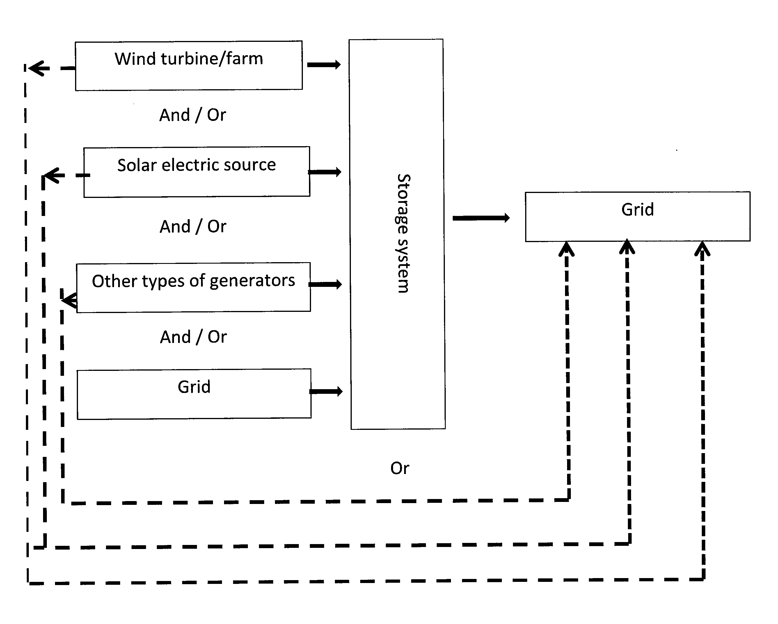
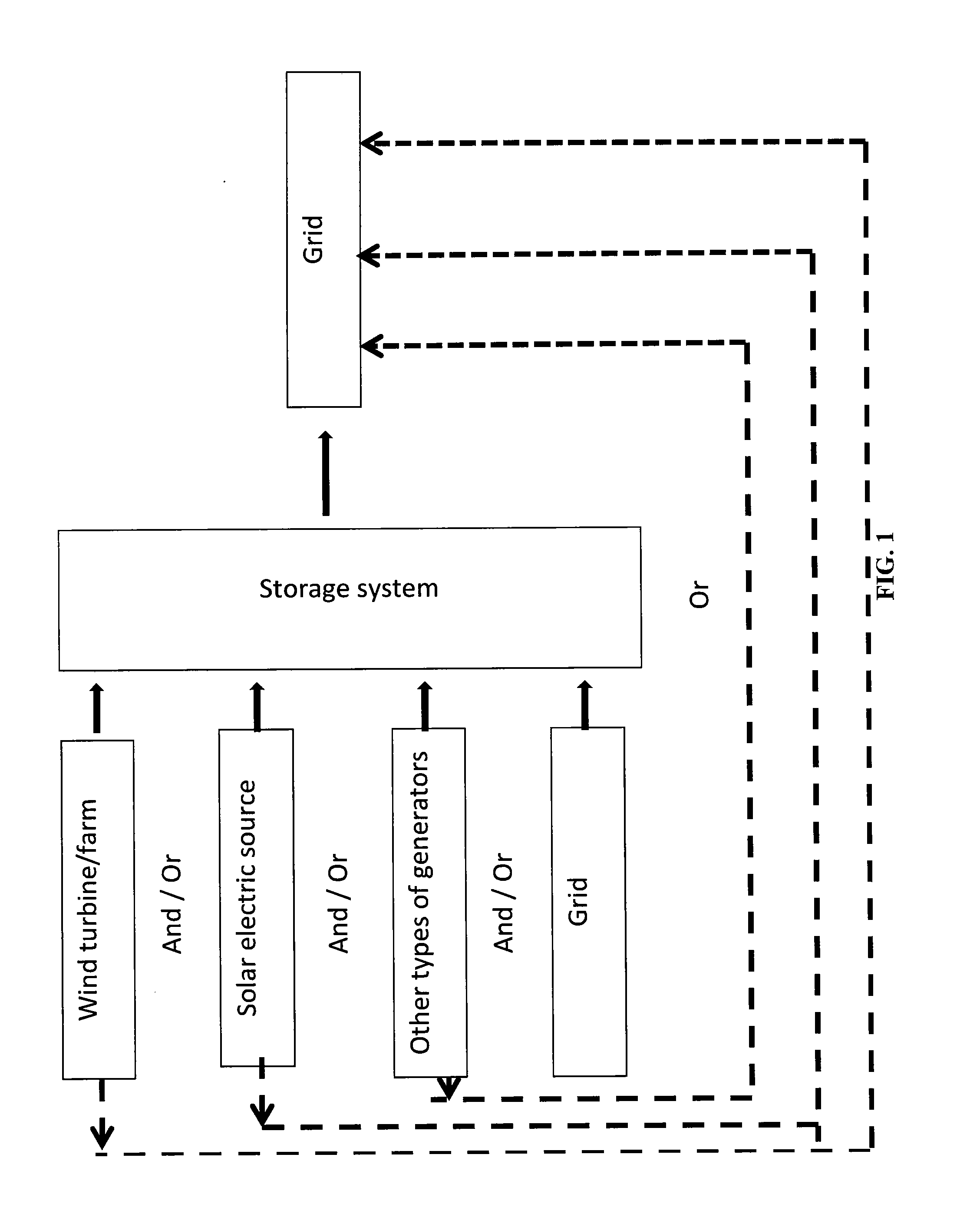
[0026]This disclosure relates to electrochemical systems, e.g., a combination of an electrical energy source and an electrical energy storage system having a regenerative fuel cell system. The electrochemical systems can achieve high power for fuel cell technology, e.g., capable of delivering power ranging from less than about 1 watt to greater than about 1 MW, while achieving low cost storage price due to the implementation of low cost reactant products. The capacity (energy) can also be adjusted to numerous configurations ranging from less than about 1 Wh to greater than about 10 MWh. The electrochemical systems of this disclosure also exhibit fast response time.

[0027]The electrochemical system of this disclosure includes a regenerative fuel cell system which generates electrical energy and reactant product from fuel and oxidizer in a fuel cell mode and which generates the fuel and oxidant from the reactant product and the electrical energy in an electrolysis mode. The system can ...


PUM

PropertyMeasurementUnit
Fractionaaaaaaaaaa
Percent by volumeaaaaaaaaaa

Abstract

This disclosure relates to electrochemical systems, e.g., a combination of an electrical energy source and an electrical energy storage system having a regenerative fuel cell system, that exhibit operational stability in harsh environments, e.g., both charging and discharging reactions in a regenerative fuel cell in the presence of an acid or a mixture of acids, or a halogen ion or a mixture of halogen ions. The electrochemical systems are capable of conducting both hydrogen evolution reactions (HERs) and hydrogen oxidation reactions (HORs) in the same system. The electrochemical systems have low cost, fast response time, and acceptable life and performance. This disclosure also relates to methods of operating the electrochemical systems containing a regenerative fuel cell system.

Description

BACKGROUND[0001]1. Field of the Disclosure[0002]This disclosure relates to electrochemical systems, e.g., a combination of an electrical energy source and an electrical energy storage system having a regenerative fuel cell system, that exhibit operational stability in harsh environments, e.g., both charging and discharging reactions in a regenerative fuel cell in the presence of an acid or a mixture of acids, or a halogen ion or a mixture of halogen ions. This disclosure also relates to methods of operating the electrochemical systems containing a regenerative fuel cell system. The electrochemical systems have low cost, fast response time, and acceptable life and performance.[0003]2. Discussion of the Background Art[0004]Fuel cells are electrochemical devices which can convert energy stored in fuels to electrical energy with high efficiencies. There are classes of fuel cells that also allow reversed operation, such that oxidized fuel can be reduced back to unoxidized fuel using elec...

Claims


Application Information

Patent Timeline
IPC IPC(8): H01M14/00H01M8/10H01M8/18C25B3/00C25B9/08C25B9/18C25B1/00H01M8/06H01M8/24C25B9/19
CPCH01M4/9083H01M4/921H01M4/926H01M4/96H01M8/0202Y02E60/50H01M8/0258H01M8/0271H01M8/186Y02E10/50Y02P70/50H01M4/90H01M8/02H01M8/04H01M8/24H01M8/1051
Inventor PELED, EMANUELBLUM, ARNON
Owner RAMOT AT TEL AVIV UNIV LTD
Why Eureka
Try Eureka