Device for measuring environmental forces and method of fabricating the same

a technology of environmental forces and sensors, applied in the direction of fluid pressure measurement, fluid pressure measurement by electric/magnetic elements, instruments, etc., can solve the problems of difficult to maintain stringent tolerances required by conventional techniques, difficult to produce small devices that are also highly sensitive to small changes in pressure, and limit the design and operation characteristics of such devices. , to achieve the effect of improving performance and reducing positional sensitivity

Inactive Publication Date: 2012-11-29
AMPHENOL THERMOMETRICS
View PDF6 Cites 17 Cited by
  • Summary
  • Abstract
  • Description
  • Claims
  • Application Information

AI Technical Summary

Benefits of technology

[0006]A device for measuring environmental forces, and a method for fabricating the same, is disclosed that comprises a device wafer, the device wafer comprising a first device layer separated from a second device layer by a first insulation layer. The first device wafer is bonded to an etched substrate wafer to create a suspended diaphragm and boss, the flexure of which is determined by an embedded sensing element. An advantage that may be realized in the practice of some embodiments of the described device and method of fabrication is that the thickness of both the diaphragm and the boss structure of a MEMS based pressure sensor can be precisely controlled using high volume planar fabrication techniques. In turn, these precise thicknesses determine the operational characteristics of the sensor, resulting in improved performance and lower positional sensitivity, especially in low pressure environments, for example, less than one atmosphere.

Problems solved by technology

Unfortunately, there has been difficulty producing smaller devices that are also highly sensitive to small changes in pressure.
Because of the small size of the devices and the thin nature of the geometries used, it is difficult for conventional techniques to maintain the stringent tolerances required, especially during high volume fabrication.
Additionally, limitations in the depth to which structures may be diffused or implanted within such MEMS devices during fabrication limit the design and operational characteristics of such devices.

Method used


Image

  • Device for measuring environmental forces and method of fabricating the same
  • Device for measuring environmental forces and method of fabricating the same
  • Device for measuring environmental forces and method of fabricating the same

Examples


Embodiment Construction

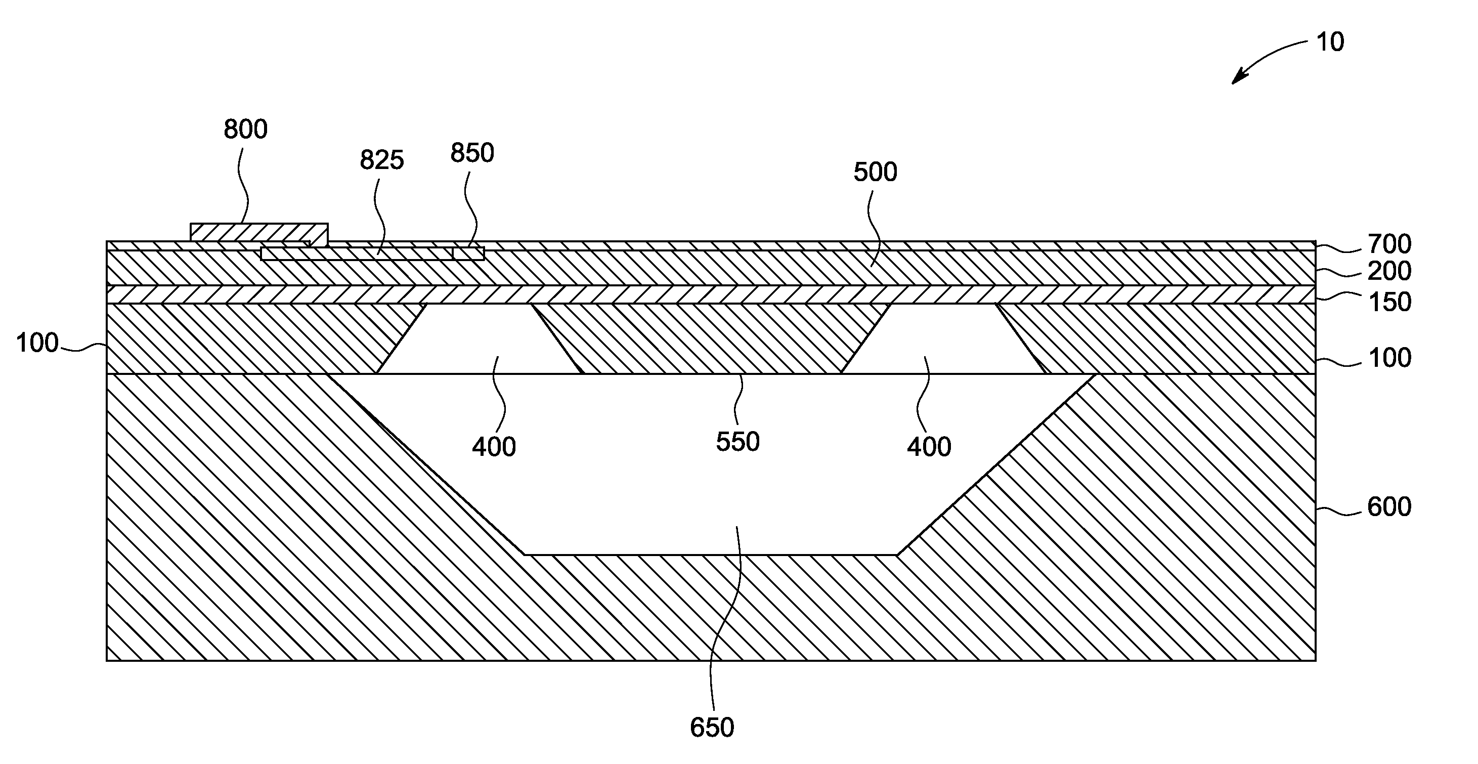
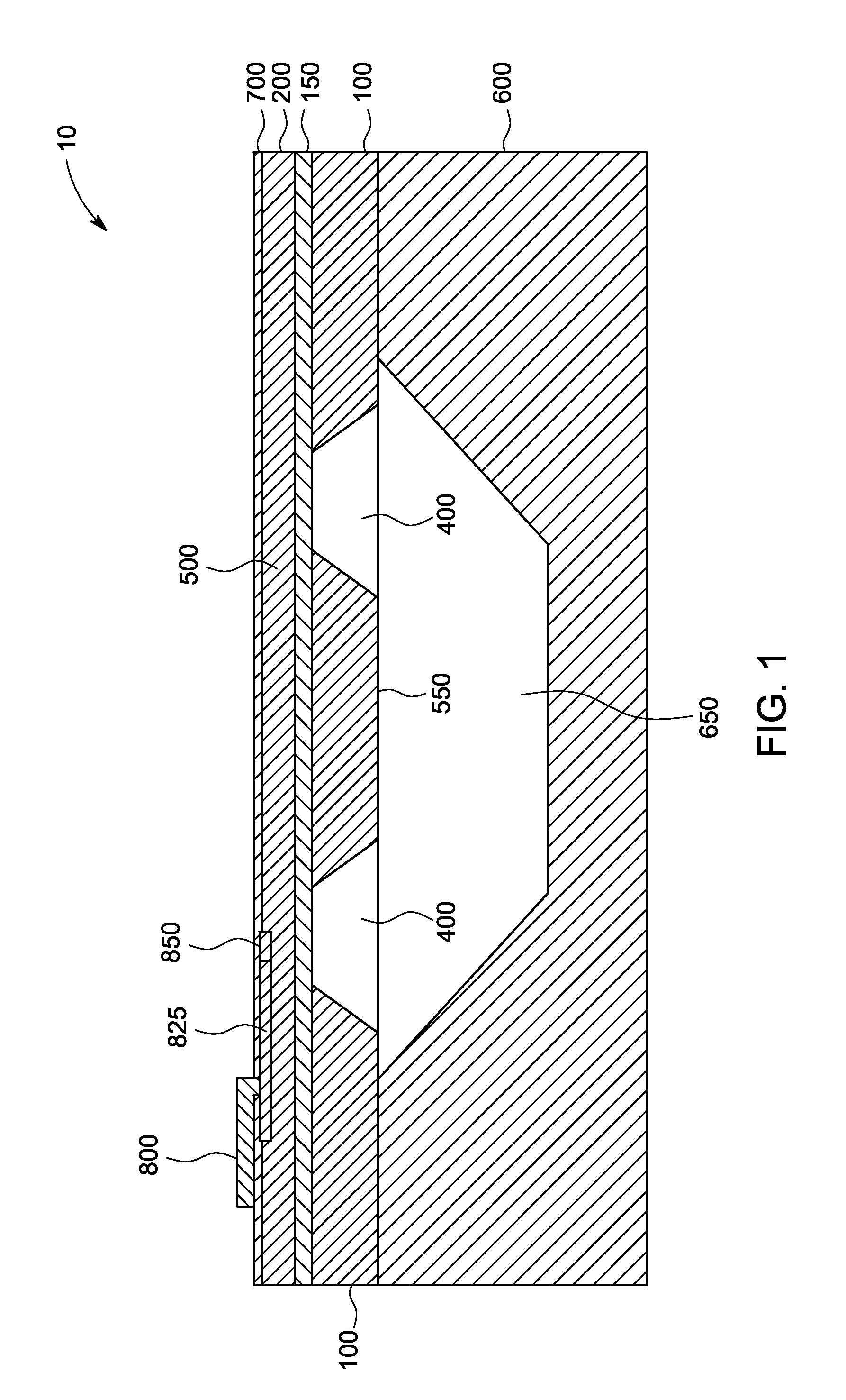
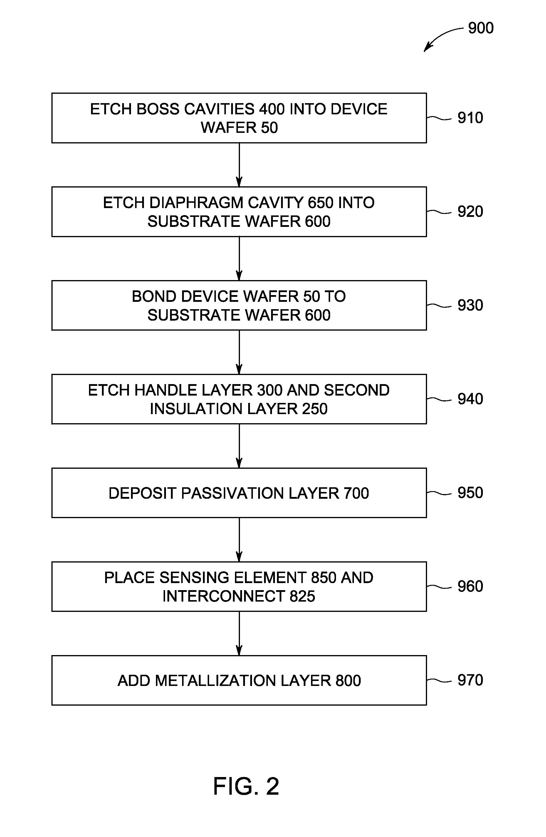
[0015]A device for measuring environmental forces, and a method for fabricating the same, is disclosed that comprises a device wafer, the device wafer comprising a first device layer separated from a second device layer by a first insulation layer. The first device wafer is bonded to an etched substrate wafer to create a suspended diaphragm and boss, the flexure of which is determined by an embedded sensing element. An advantage that may be realized in the practice of some embodiments of the described device and method of fabrication is that the thickness of both the diaphragm and the boss structure of a MEMS based pressure sensor can be precisely controlled using high volume planar fabrication techniques. In turn, these precise thicknesses determine the operational characteristics of the sensor, resulting in improved performance and lower positional sensitivity, especially in low pressure environments, for example, less than one atmosphere.

[0016]An exemplary pressure sensor can be ...


PUM

PropertyMeasurementUnit
electrical communicationaaaaaaaaaa
absolute pressureaaaaaaaaaa
differential pressureaaaaaaaaaa

Abstract

A device for measuring environmental forces, and a method for fabricating the same, is disclosed that comprises a device wafer, the device wafer comprising a first device layer separated from a second device layer by a first insulation layer. The first device wafer is bonded to an etched substrate wafer to create a suspended diaphragm and boss, the flexure of which is determined by an embedded sensing element.

Description

BACKGROUND OF THE INVENTION[0001]The subject matter disclosed herein relates to semiconductor microelectromechanical based sensors (MEMS) that can be used to detect small forces or flexures generated from environmental factors, for example mechanical stress, chemo-mechanical stress, thermal stress, electromagnetic fields, and the like. More particularly, the subject matter disclosed herein relates to a device for sensing pressure and a method of fabricating the same.[0002]Advances in semiconductor microelectronic based sensors have served greatly to reduce the size and cost of such sensors. The electrical and mechanical properties of silicon microsensors, as well as silicon micromachining and semiconductor microelectronic technologies, have improved. For instance, micromachined silicon pressure sensors, acceleration sensors, flow sensors, humidity sensors, microphones, mechanical oscillators, optical and RF switches and attenuators, microvalves, ink jet print heads, atomic force mic...

Claims


Application Information

Patent Timeline
Patent Type & Authority Applications(United States)
IPC IPC(8): G01L9/00G01L9/06H05K13/04G01L7/08
CPCG01L9/0047B81B2201/0264Y10T29/49002B81C1/00182Y10T29/42B81B2203/0127
Inventor GAMAGE, SISIRA KANKANAMMANTRAVADI, NARESH VENKATA
Owner AMPHENOL THERMOMETRICS
Why Eureka
Try Eureka