Medical Procedure Localizing Aid

Inactive Publication Date: 2012-11-29
TARGET TAPE
View PDF22 Cites 56 Cited by
  • Summary
  • Abstract
  • Description
  • Claims
  • Application Information

AI Technical Summary

Benefits of technology

[0015]The apparatus and method of the present and illustrated inventions are based on a device that defines an improved means and method of non-invasively locating a procedure site on a patient prior to surgery. The inventive apparatus may be used in connection with numerous types of medical imaging scans, such as, but not limited to: X-rays, computerized tomography, position emission tomography, ultrasound and nuclear magnetic resonance imagining. The aid will produce reference marks on both the patient and the medical imaging scan. The aid is utilized in two phases. The first phase involves the aid attached to the body before a medical imaging scan. The resulting image from the scan shows a visual of both the internal anatomy and the opaque indicia from the aid itself—the word opaque meaning herein a material that would appear on the medical image. The second phase involves the removal of the aid. Upon removal of the aid an identical or correlating visual mark of the indicia will be on the body and may or may not be of a marking material opaque to the medical imaging scan. As a result, the medical professional may reliably use the combination of th

Problems solved by technology

This method is prone to inaccuracy and often requires an extension of the incision or working awkwardly through an angled trajectory.
In some instances, the medical professional may even accidentally perform the procedure on the wrong area because the site of the incision was inaccurate.
The locational marks on the scan are not useful if they can no longer be referenced to on the body.
This device will show as a line on the x-ray image, but does not provide direct locational guidance on the body when the patient enters the operating room.
The pellet also obstructs the medical professional from marking the skin of the incision area with their surgical pen.
The pellets must be removed, and thus rendered useless, if the medical professional marks their area of interest.
This device is limited to small shapes for the foot and must be removed during the procedure.
Using a free hand pen to mark the skin for locational purposes is messy, limits the precision of designs and the accuracy of consistent spacing.
This method is time con

Method used


Image

  • Medical Procedure Localizing Aid
  • Medical Procedure Localizing Aid
  • Medical Procedure Localizing Aid

Examples


Embodiment Construction

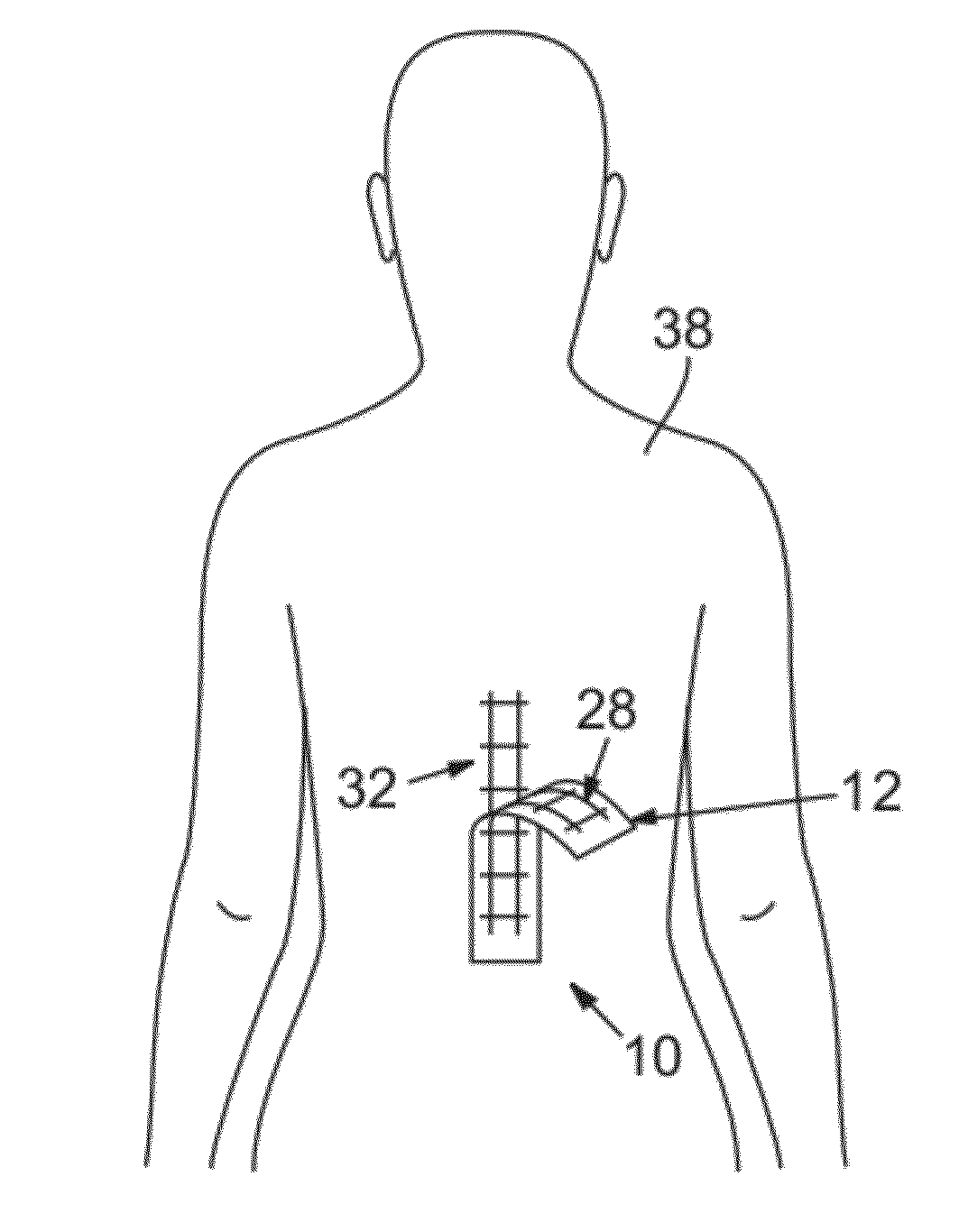
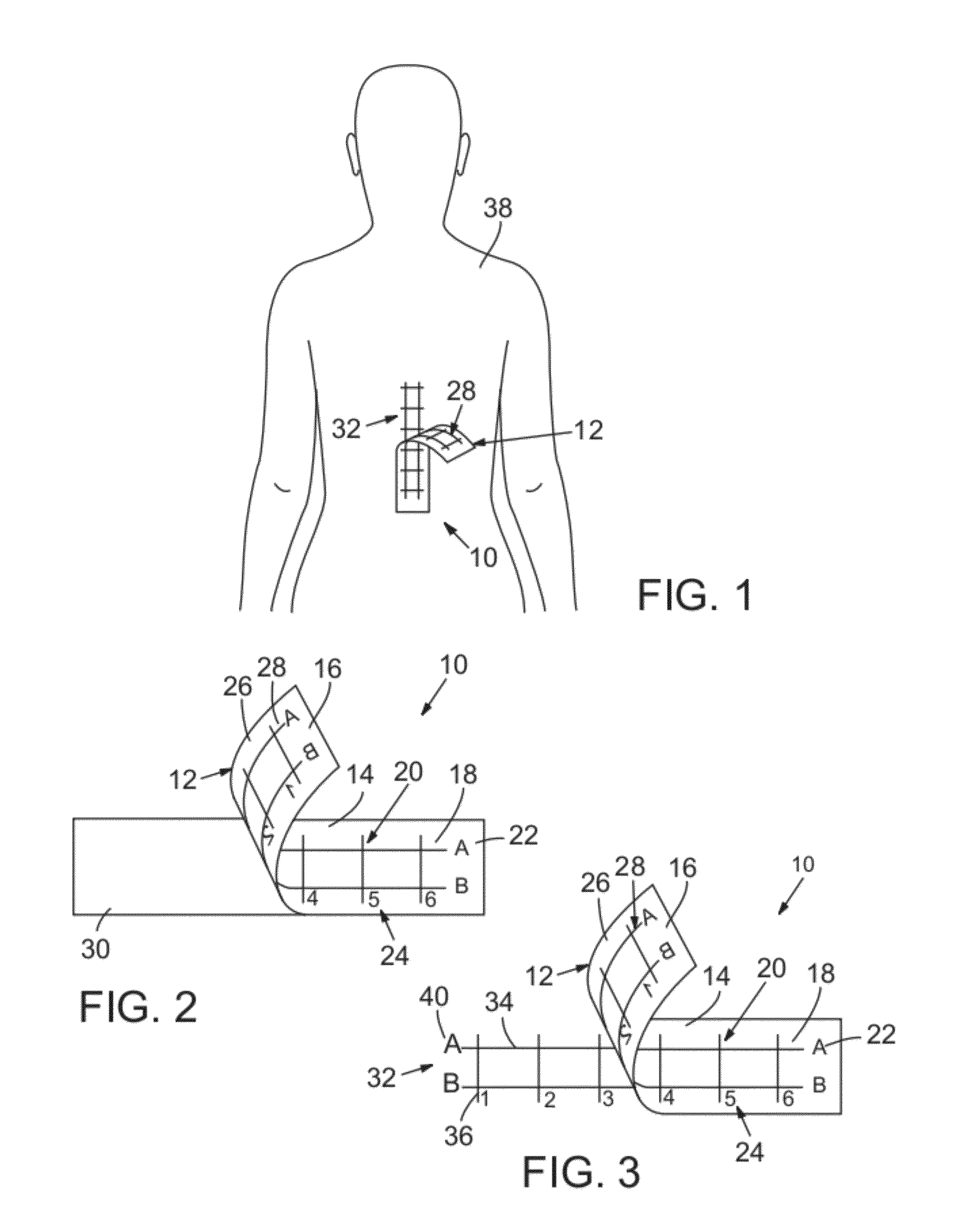
[0030]In a most preferred embodiment, the medical procedure localizing aid 10 according to the present invention is a sterile, flexible adhesive-backed sheet or substrate having opposed top and bottom surfaces. As a naming convention, for purposes herein the “top” or “upper” surface of the localization aid is the surface of the sheet that is exposed and faces away from the patient when the localization aid is in place. The “bottom” or “lower” surface is then the opposite side of the sheet—that is, the side of the sheet on which an adhesive material has typically been applied and which is applied to the patient's skin when the localization aid is in place. The actual geometric configuration of the sheet can range from a variety of different shapes and sizes. This can range from a large area to cover the chest and back to small narrow strips for fingers and toes, or any other convenient size or shape. The top surface will suspend indicia that is opaque to medical imaging scans—as note...


PUM


Abstract

A medical procedure localization aid produces reference marks on both the patient and the medical imaging scan. The aid is defined by a substrate sheet having indicia on one side that is opaque to medical imaging radiation and indicia on a second side that is transferable to a patient. The indicia on the first side is displayed on the scan image and the indicia on the second side is imprinted on the patient. By visualizing the location of a target on the scan image relative to the indicia on the scan image and comparing that with indicia on the patient, a medical professional may reliably locate where a medical procedure should be performed.

Description

FIELD OF THE INVENTION[0001]This invention relates to apparatus and methods used in the medical field, and more specifically to apparatus and methods for medical procedure localization.BACKGROUND[0002]A medical imaging scan, such as an X-ray, computerized tomography, position emission tomography, and / or nuclear magnetic resonance imagining, is commonly utilized first to determine if a surgical procedure is necessary. The medical professional such as a doctor, surgeon, radiologist, nurse, technician, veterinarian or clinical researcher relies on this image to view the precise internal information of the patient. If the medical image shows irregularities, the medical professional may then conclude that a medical procedure is necessary. When the precise area of interest is determined on the medical image, the medical professional will have to perform their procedure directly above this area. Examples of these various procedures include surgical incisions to treat fractures, spinal and ...

Claims


Application Information

Patent Timeline
IPC IPC(8): A61B6/00
CPCA61B19/54A61B2017/00951A61B6/508A61B2019/5466A61B2019/5495A61B2019/545A61B2090/3995A61B90/39A61B2090/395A61B2090/3966
Inventor O'NEILL, COLIN
Owner TARGET TAPE
Why Eureka
Try Eureka