
Method and Device for Testing a Capacitively Operating Measuring Device, Which Is Designed for the Detection of Phase Boundaries, and Correspondingly Equipped Laboratory Apparatus

a capacitively operating and measuring device technology, applied in the direction of volume measurement apparatus/methods, capacity measurement calibration, liquid/fluent solid measurement, etc., can solve the problem of high spatial compaction of individual components, shortening the measurement sequence with respect to time, and increasing the precision and complexity of the laboratory apparatus. the effect of time-consuming

Active Publication Date: 2012-12-06
TECAN TRADING AG
View PDF2 Cites 10 Cited by
  • Summary
  • Abstract
  • Description
  • Claims
  • Application Information

AI Technical Summary

Benefits of technology

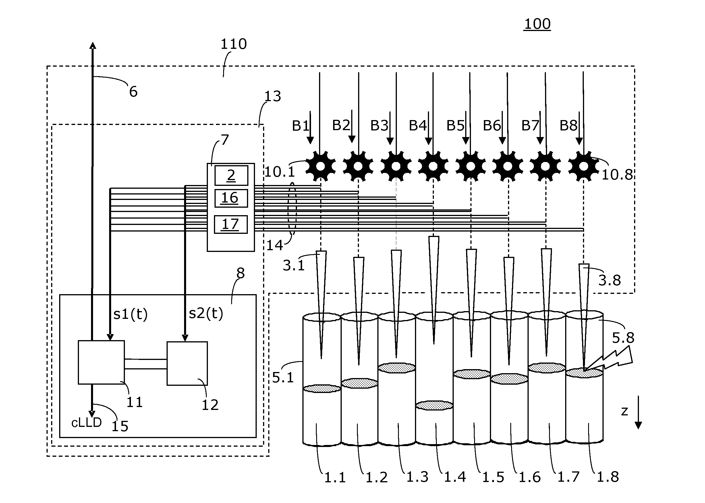
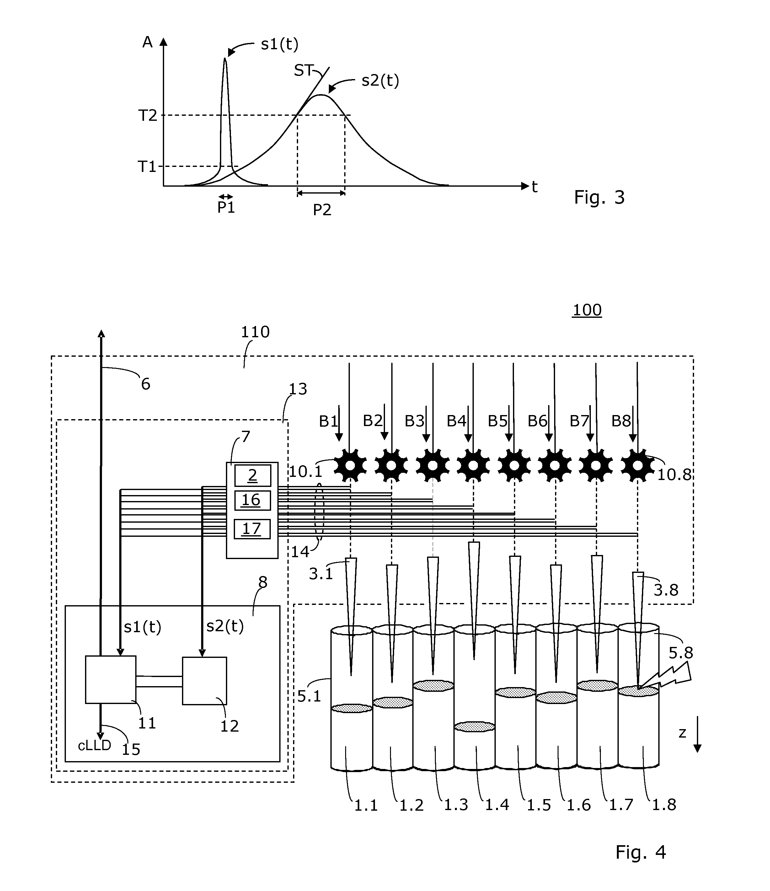
[0033]It is an advantage of the present invention that various functions can be sequentially tested and various types of errors can be recognized. This is performed in all embodiments in a so-called contactless, or dry method, respectively, i.e., no liquid has to be touched during the performance of the testing method, or no plunging procedure must be executed. The method according to the invention is therefore referred to hereafter as a method for dry testing, in order to express this essential aspect. The testing of the electrical connections is performed according to the invention without touching a reference body or medium. The testing of the electrical connections is preferably performed according to the invention in a dry manner, i.e., no phase boundary must be searched for or penetrated for the testing.
[0034]The method of the invention is less time-consuming and susceptible to interference than previously known methods.
[0035]According to the invention, the required tests are performed in a contactless manner (preferably liquid-independent), so that the probe or probes are neither contaminated with liquids nor can the probes or their coating, respectively, be damaged by touching a solid contact surface.
[0036]According to the invention, no special arrangement of carriers and labware on the worktable of the laboratory apparatus is necessary.
[0037]According to the invention, the method can be performed directly over an optional washing station, which is located on the worktable. In this way, the customer-specific equipment of the worktable with carriers does not have to be changed.
[0038]According to the invention, the method can be performed within a longer sequence of pipetting processes as an intermediate control step (“in process control”), e.g., over a washing station.

Problems solved by technology

In recent years, laboratory apparatuses have become more and more precise and complex.
This results in a high spatial compaction of the individual components and a shortening of the measurement sequences with respect to time.
This compaction not only causes mechanical and other design problems, but rather also the precision of the electronic analyzing capability, the mutual influence of adjacent measuring channels, and other aspects may result in problems.
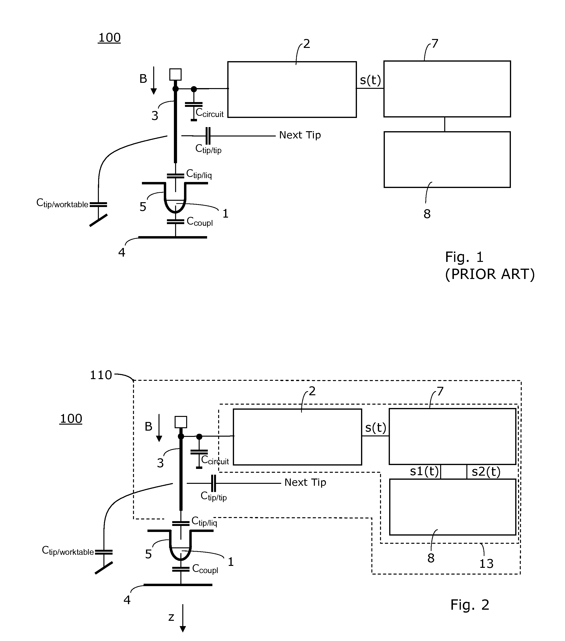
The higher the degree of integration of such capacitively operating measuring devices, the more problematic it is to be able to recognize the capacitance changes to be measured because of stray capacitances, crosstalk between adjacent channels, and capacitance changes because of moving electrical supply lines.
Nonetheless, it has been heretofore unavoidable to change the customer-specific equipment of the worktable with carriers, to put on the test-specific carriers, and to reproduce the exact customer equipment after the test.
It is a disadvantage of this approach that the time and work expenditure is relatively large.
It is considered to be a further disadvantage that special worktable equipments having carriers and labware must be used.
It is to be considered that, e.g., in automated pipetting systems or devices, numerous situations can occur, which cannot be resolved automatically by previous automated pipetting systems or apparatuses.

Method used


Image

  • Method and Device for Testing a Capacitively Operating Measuring Device, Which Is Designed for the Detection of Phase Boundaries, and Correspondingly Equipped Laboratory Apparatus
  • Method and Device for Testing a Capacitively Operating Measuring Device, Which Is Designed for the Detection of Phase Boundaries, and Correspondingly Equipped Laboratory Apparatus
  • Method and Device for Testing a Capacitively Operating Measuring Device, Which Is Designed for the Detection of Phase Boundaries, and Correspondingly Equipped Laboratory Apparatus

Examples


Embodiment Construction

[0075]Advantageous embodiments of the invention are described hereafter, these being exemplary embodiments. These comprise both various implementations of the overall invention, and also assemblies and individual parts of the invention. Fundamentally, the described assemblies and individual parts of the various embodiments may be combined with one another, or the assemblies and individual parts of individual embodiments may be replaced by the assemblies and individual parts of other embodiments, respectively. The combinations formed in this case can require smaller adaptations, which are routine to any person skilled in the art and are therefore not described in greater detail, for example, to allow cooperation or interlocking of the assemblies and individual parts.

[0076]The term phase boundary is used for boundaries between two or more media, which have different dielectric constants. These are especially liquid-liquid and gas-liquid phase boundaries.

[0077]The term module is used h...


PUM


Abstract

A device has at least one channel for detecting the phase boundary between media in a liquid container and has a probe which can be fed in the direction of the phase boundary and a circuit which processes a signal of the probe to detect a capacitance change. The device includes a testing module which executes an infeed movement of the probe. The testing module performs an analysis of the signal of the channel, and makes a connection statement about the electrical connection between the probe and the measuring circuit. The testing of the electrical connections is performed in a dry manner, i.e., a phase boundary does not have to be searched for or penetrated for the testing.

Description

FIELD OF THE INVENTION [0001]The invention is directed to a method for testing a capacitively operating measuring device, which is designed for the detection of phase boundaries, and correspondingly equipped laboratory apparatuses. In particular it is directed to a function test of such a measuring device and a laboratory apparatus, which are designed for detecting a liquid level in a liquid container.BACKGROUND OF THE INVENTION[0002]There are numerous laboratory systems and medical and pharmaceutical apparatuses in which it is important to ascertain the fill level in test tubes, microplates, or the like. There are also applications which relate to the detection of liquid-liquid phase boundaries. The term phase boundary is used hereafter both for transitions between gaseous and liquid media (gas-liquid phase boundary) and for transitions between various liquid media (liquid-liquid phase boundary).[0003]In particular if the automation of measuring or experimental sequences is a goal,...

Claims


Application Information

Patent Timeline
IPC IPC(8): G01F25/00
CPCG01F23/263G01F23/265G01F25/0076G01N2035/1025G01N35/1011G01N35/1065G01N35/00623G01F25/24
Inventor MARKI, SARAHCORS, NICOLASSTRUCHEN, THOMAS
Owner TECAN TRADING AG
Learn More