X-ray tube and radiation imaging apparatus

a radiation imaging and tube technology, applied in the field of x-ray tubes, can solve the problems of difficult downsizing, difficult diameter of glass tubes, and inability to resist voltage, and achieve the effect of improving voltage withstand capability

Inactive Publication Date: 2012-12-06
CANON KK
View PDF4 Cites 35 Cited by
  • Summary
  • Abstract
  • Description
  • Claims
  • Application Information

AI Technical Summary

Benefits of technology

[0010]In consideration of the above, it is an object of the present invention to provid

Problems solved by technology

With conventional X-ray tubes, voltage withstand capability have been an issue in achieving downsizing and weight reduction.
In such a case, depending on a distance between the outer surface of the focusing electrode and the inner wall of the insulating tube, a discharge may occur between the outer surface of the focusing elect

Method used


Image

  • X-ray tube and radiation imaging apparatus
  • X-ray tube and radiation imaging apparatus
  • X-ray tube and radiation imaging apparatus

Examples


first embodiment

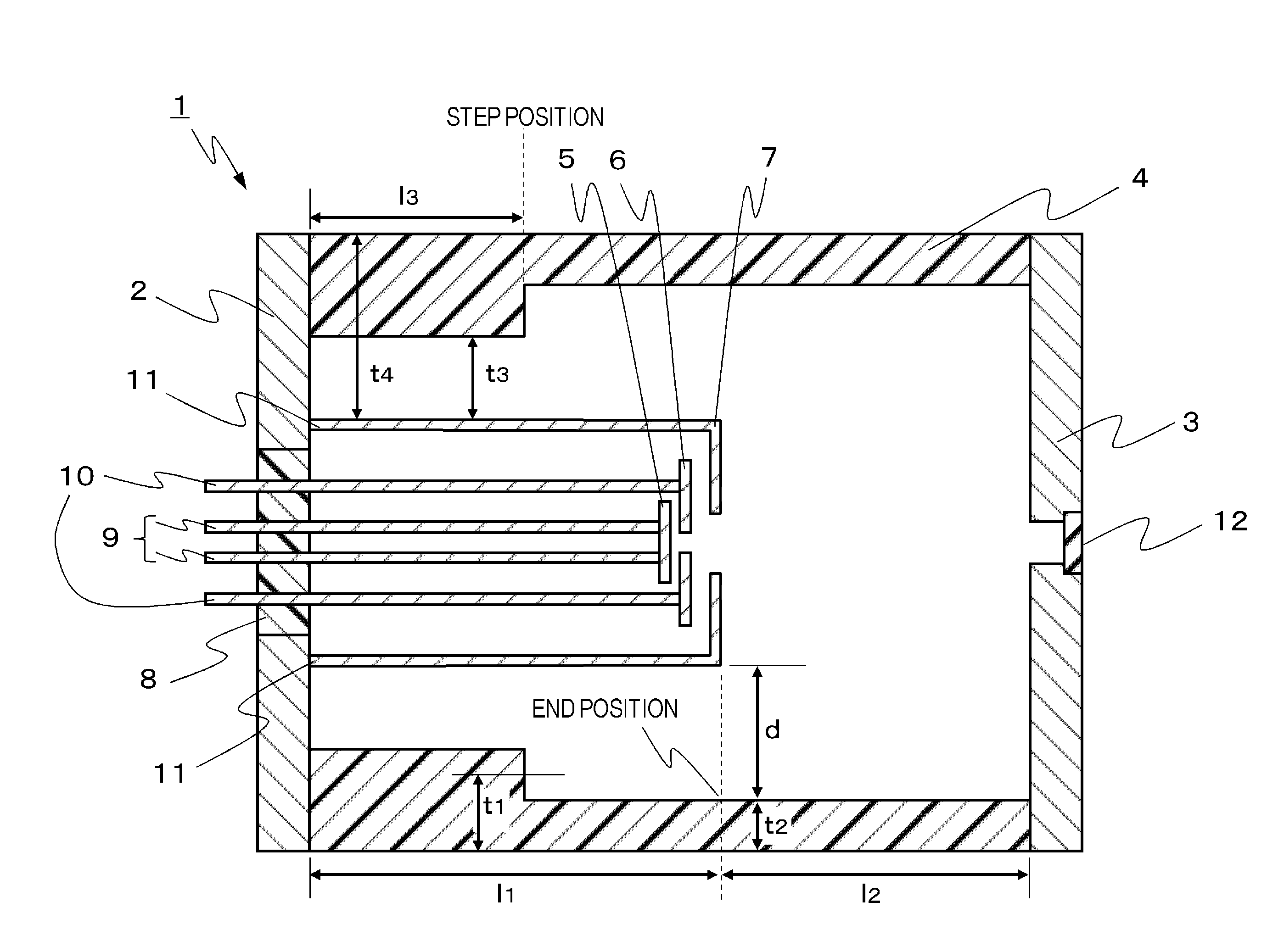
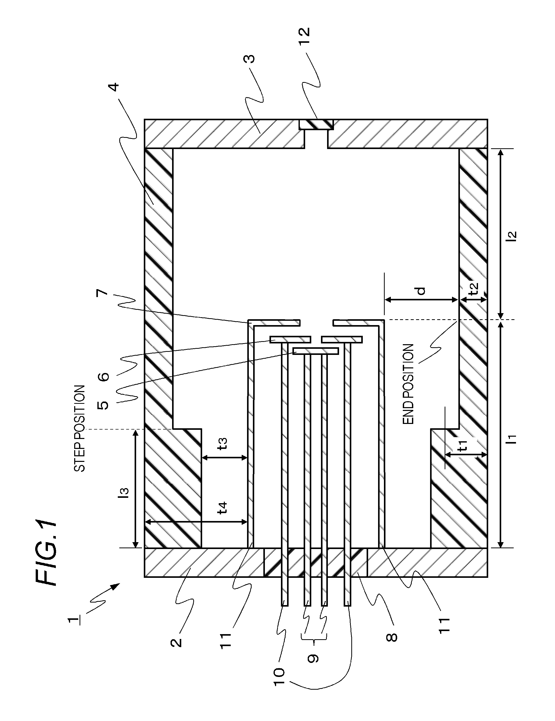
[0021]FIG. 1 is a configuration diagram of an X-ray tube according to the present embodiment and is a sectional schematic diagram of the X-ray tube according to the present embodiment cut along a plane including a cathode, an anode, an insulating tube, an electron gun, and a target.

[0022]An X-ray tube 1 is a vacuum tube comprising an envelope having a cathode 2 at one end and an anode 3 at another end of a barrel of a tubular insulating tube 4, an electron gun arranged inside the envelope, and a target arranged at the anode.

[0023]The cathode 2 is connected to the electron gun shaped so as to protrude from the cathode 2. The electron gun comprises an electron source 5, a grid electrode 6, a focusing electrode 7, an electron source driving terminal 9, a grid electrode terminal 10, and a focusing electrode terminal 11, and a gap is provided between an outer surface of the electron gun and an inner wall of the insulating tube 4. The term “outer surface of the electron gun” as used in th...

first example

EVALUATION OF FIRST EXAMPLE

[0044]Between the first example and the first comparative example, ratios of field intensity between the end position and the anode-side end of the focusing electrode were 1:1.02 or, in other words, approximately equal to each other. In addition, a measurement of withstand voltages of the X-ray tube according to the first example and the X-ray tube according to the first comparative example revealed similar withstand voltages. Consequently, the X-ray tube according to the first example had achieved downsizing of 13% in volume ratio compared to the first comparative example without sacrificing voltage withstand capability.

SECOND EXAMPLE

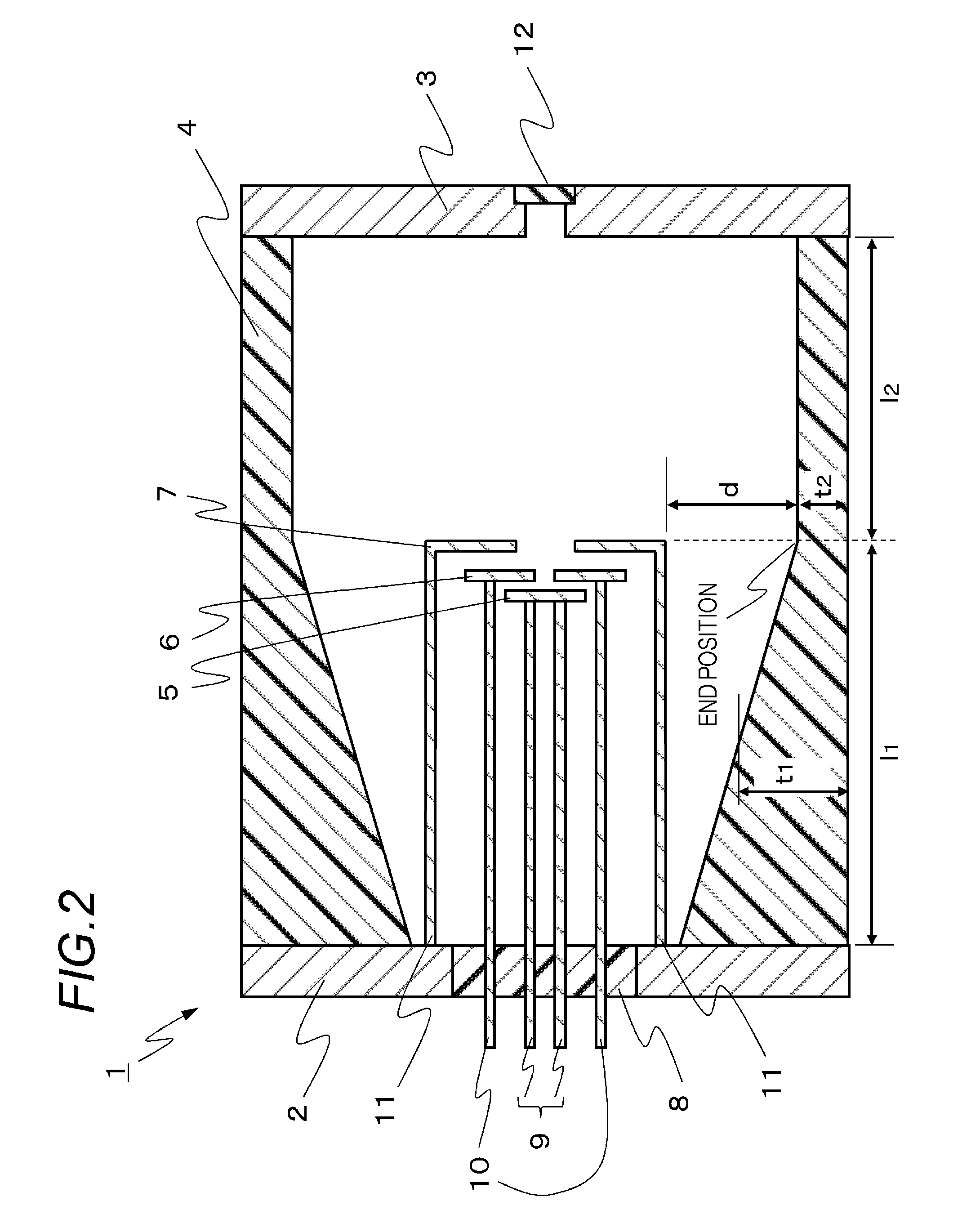
[0045]A configuration diagram of an X-ray tube according to the present example is shown in FIG. 2. The X-ray tube according to the present example differs from the first example in the outer diameters of the cathode 2, the anode 3, and the insulating tube 4, and in the shape of the inner wall of the insulating tube 4. Mater...

second example

EVALUATION OF SECOND EXAMPLE

[0047]Between the second example and the first example, ratios of field intensity between the end position and the anode-side end of the focusing electrode were 0.97:1 or, in other words, slightly lower in the second example. In addition, a measurement of withstand voltages of the X-ray tube according to the second example and the X-ray tube according to the first example revealed similar withstand voltages. Consequently, the X-ray tube according to the second example had achieved downsizing of approximately 20% in volume ratio compared to the first comparative example without sacrificing voltage withstand capability.

THIRD EXAMPLE

[0048]The X-ray tube according to the present example uses the same materials and has the same configuration as the second example with the exception of borosilicate glass being used as the insulating tube 4.


PUM


Abstract

An X-ray tube comprises: an envelope which has a cathode at one end and an anode at another end of a barrel of a tubular insulating tube and which has a sealed interior; an electron gun which is arranged inside the envelope and has a shape that protrudes from the cathode; and a target which is electrically connected to the anode and generates X-rays when being irradiated with electrons emitted from the electron gun. With reference to an end position that is a projection of a position of an end on the anode side of the electron gun onto an inner wall of the insulating tube, a mean wall thickness of the barrel is greater on the cathode side than on the anode side.

Description

BACKGROUND OF THE INVENTION[0001]1. Field of the Invention[0002]The present invention relates to an X-ray tube applicable to medical and industrial X-ray generators and, in particular, to a transmissive X-ray tube that uses a transmissive target.[0003]2. Description of the Related Art[0004]A transmissive X-ray tube is a vacuum tube comprising a cathode, an anode, and an insulating tube. X-rays are generated by accelerating electrons emitted from an electron source of the cathode with a high voltage applied between the cathode and the anode and irradiating a target arranged at the anode with the accelerated electrons. The generated X-ray is emitted to the outside from the target that doubles as an X-ray extraction window.[0005]With conventional X-ray tubes, voltage withstand capability have been an issue in achieving downsizing and weight reduction.[0006]Japanese Patent Application Laid-open No. H09-180660 discloses a transmissive X-ray tube having voltage withstand capability improv...

Claims


Application Information

Patent Timeline
IPC IPC(8): H01J35/16G01N23/04
CPCH01J35/06H01J35/08H01J2235/16H01J2235/087H01J35/16H01J35/066H01J35/116
Inventor YAMAZAKI, KOJINOMURA, ICHIROAOKI, SHUJIOGURA, TAKAOSATO, YASUEYANAGISAWA, YOSHIHIROUEDA, KAZUYUKITAMURA, MIKI
Owner CANON KK
Why Eureka
Try Eureka