
Dual fuel engine system

a fuel system and engine technology, applied in the direction of electrical control, process and machine control, instruments, etc., can solve the problems of voiding the manufacturer's warranty, several additional limitations, and complex system, and achieve the effect of quick installation

Inactive Publication Date: 2012-12-06
ECODUAL
View PDF8 Cites 148 Cited by
  • Summary
  • Abstract
  • Description
  • Claims
  • Application Information

AI Technical Summary

Benefits of technology

[0012]The preferred system of the present invention does not need to be connected to any of the vehicle sensors and does not require complex algorithms which attempt to make sense of the sensor signals. A dual fuel system in accordance with the subject invention, in one preferred embodiment, is able to operate on 80% natural gas with no power loss on hills or during acceleration. The system is quickly installed and fairly inexpensive. The system does not void the engine warranty and requires no mechanical or electrical modifications to the original diesel engine or emission system.

Problems solved by technology

Such systems can void the manufacturer's warranty and also suffer from several additional limitations.
Such a system can be highly complex.
Mapping or calculating the optimal ratio of diesel fuel and natural gas based on these sensor signals can be difficult.
Furthermore, intercepting and interpreting sensor signals and / or “tricking” an OEM ECM may be deemed by the OEM and / or government agencies (for example, the E.P.A) as problematic and / or undesirable.

Method used

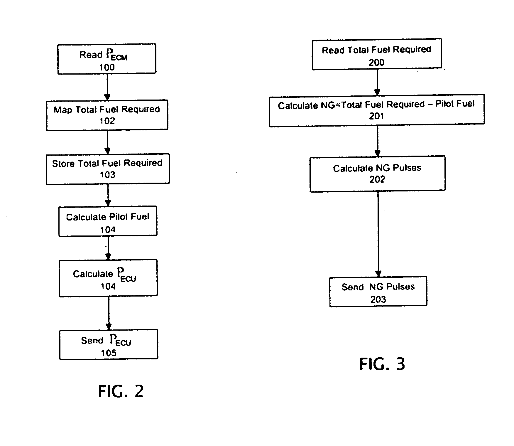

Image

  • Dual fuel engine system
  • Dual fuel engine system
  • Dual fuel engine system

Examples


Embodiment Construction

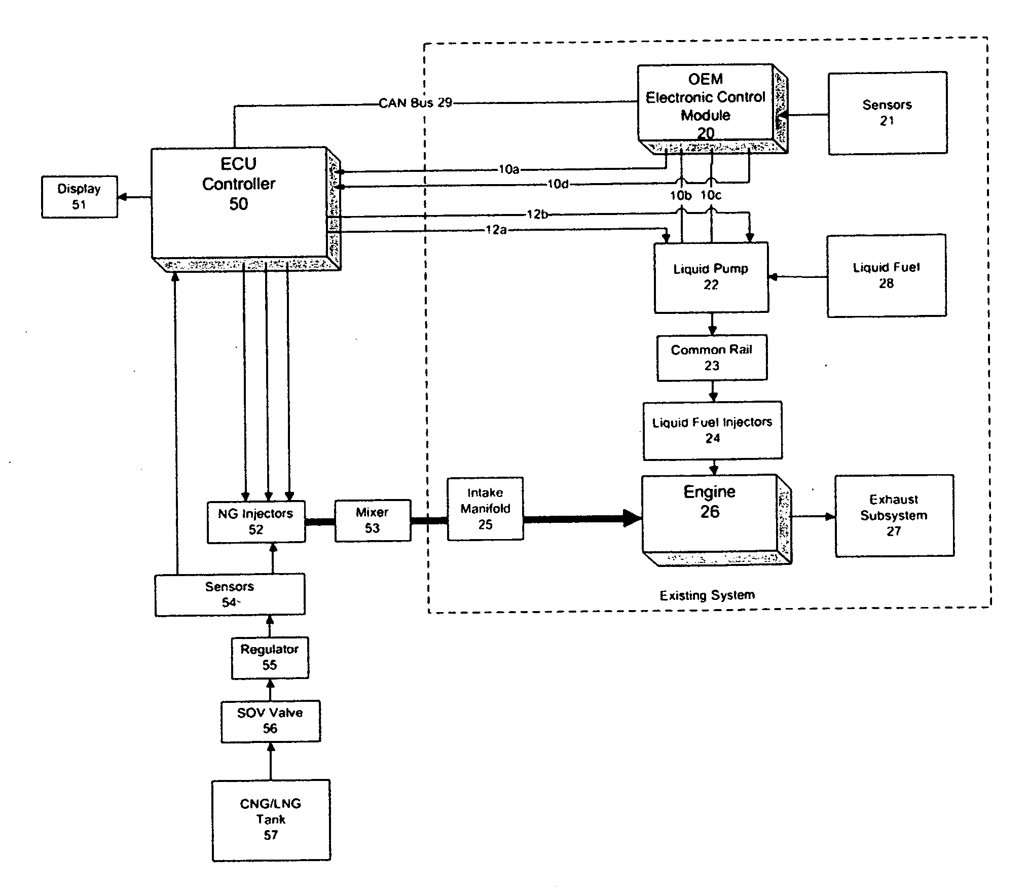
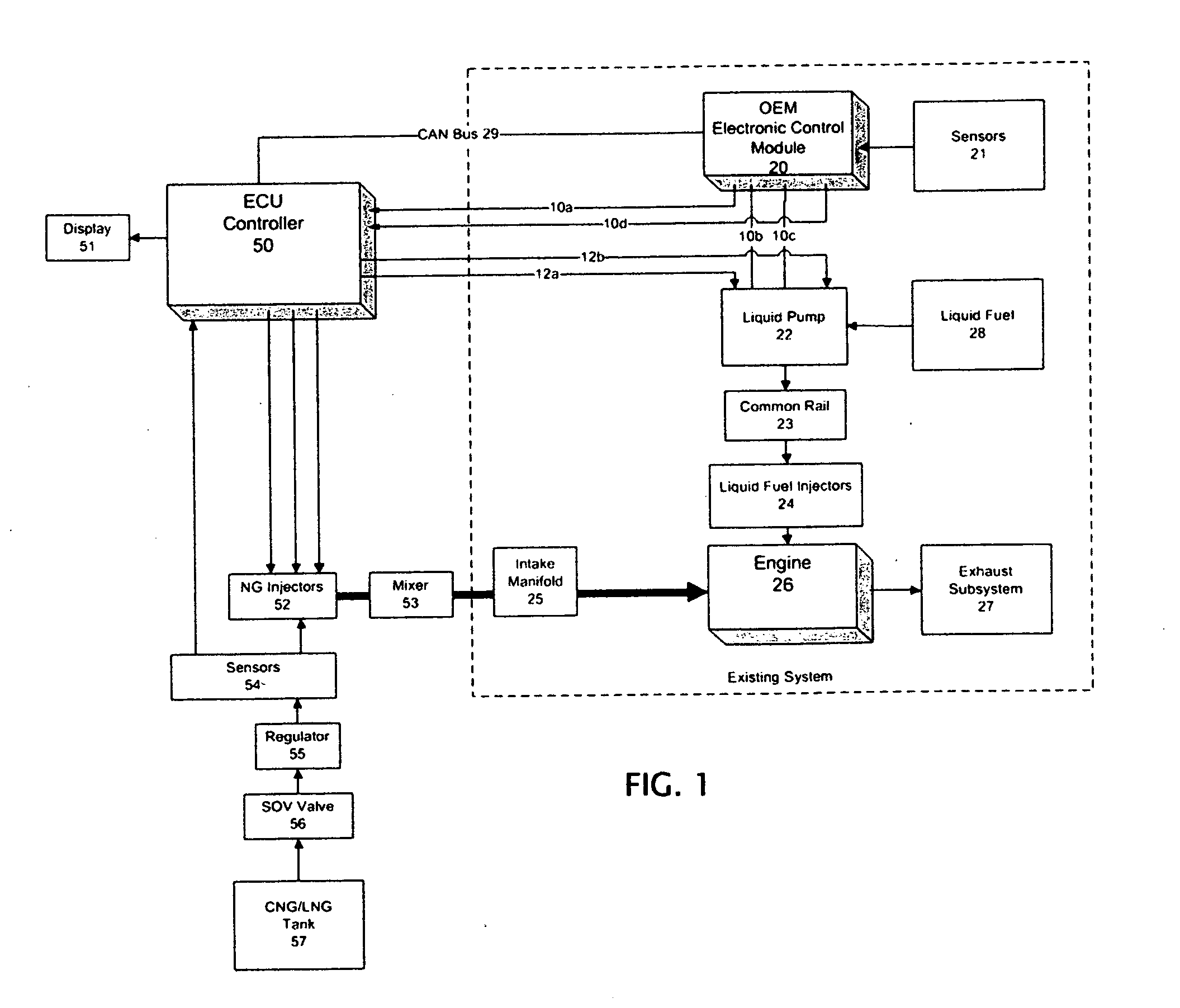
[0028]FIG. 1 depicts an example of a dual fuel system 10 for engine 26, typically a diesel engine or “compression internal combustion engine”. In some embodiments, there are a plurality of cylinders, with a piston in each cylinder defining a combustion chamber between a cylinder head and the piston. The piston is connected to a crank shaft in a conventional manner. Inlet and exhaust valves are provided and may be actuated by a cam shaft rotated by the crank shaft to control the supply of air / fuel mixture to and the exhaust of combustion products from the combustion chamber via exhaust subsystem 27. Gases may be supplied to and exhausted from engine 26 via an air intake manifold and an exhaust manifold. A turbo charger may be included as well.

[0029]In this example, there is a fuel supply subsystem whereby liquid fuel, e.g. diesel fuel, is presented to engine 26 from a tank 28 via pumps and the like represented at 22, in this example, to common rail supply 23 and injectors 24. In othe...


PUM


Abstract

A dual fuel system employs a liquid fuel supply subsystem and a gaseous fuel supply subsystem for an engine. The liquid fuel supply subsystem supplies liquid fuel to the engine and an electronic control module is configured to control, via one or more liquid fuel control signals, the amount of liquid fuel supplied to the engine based on one or more sensor signals. A gaseous fuel supply subsystem is configured to supply gaseous fuel to the engine and an electronic controller subsystem responsive to liquid fuel control signal(s) determines, based on the liquid fuel control signals, a modified amount of liquid fuel and an amount of gaseous fuel to be supplied to the engine for dual fuel operation.

Description

BACKGROUND OF THE INVENTION[0001]1. Field of the Invention[0002]The present invention relates to the field of fuel systems for engines. The invention herein relates more particularly to a dual fuel system that combines a liquid fuel such as diesel fuel and a gaseous fuel such as natural gas.[0003]2. Background Art[0004]Dual fuel engines are disclosed for example, in U.S. Pat. Nos. 6,901,889; 7,270,089; and in U.S. Patent Publication No. 2010 / 0332106; and WO 2007 / 115594 all incorporated herein by this reference.[0005]Such duel fuel engines often include a diesel engine operating on both diesel fuel and natural gas (e.g., CNG or LNG). The diesel fuel is usually delivered to a common rail and electronically controlled injectors or to unit injectors from a tank via pump(s) and valve(s) or via other components of a liquid fuel supply subsystem. The diesel fuel amount is controlled, in an unmodified engine, at least in part by a vehicle's electronic control module (ECM) based on a variety...

Claims


Application Information

Patent Timeline
IPC IPC(8): F02D41/30
CPCF02D41/266F02D41/3094F02D19/061Y02T10/36F02D19/10F02D41/0027F02D2400/11F02D19/0623Y02T10/30
Inventor PARDO, LEO G.BERRY, JOHN G.RANON, URI
Owner ECODUAL
Learn More