Method and device for leak testing in an automated electrohydraulic clutch system in a motor vehicle

a technology of electrohydraulic clutch and leak detection, which is applied in the direction of fluid-tightness measurement, instrumentation, and measurement of fluid loss/gain rate, can solve the problems of incorrect setting of clutch travel for opening and closing, prolonging etc., to prevent inadequate torque setting, rapid and reliable detection, and prolong the service life of the clutch

Inactive Publication Date: 2012-12-13
ROBERT BOSCH GMBH
View PDF19 Cites 8 Cited by
  • Summary
  • Abstract
  • Description
  • Claims
  • Application Information

AI Technical Summary

Benefits of technology

[0007]The method of the present invention for leak testing of an automated clutch system in a motor vehicle has an advantage that a defective system is detected reliably and rapidly and may optionally be replaced. Since the leak in the clutch system is detected by measuring pressure in the electromechanical actuator, it is ensured that a lack of agreement in the travel correlation between the electromechanical actuator and the clutch may be detected rapidly and reliably by comparing the pressure measurement to a characteristic clutch curve. Such lack of agreement leads to the clutch travel necessary for opening and closing not being set correctly. The timely detection of such a disturbance prevents the clutch from being operated in a slipping state for a relatively long time. Thus, the early detection of the defect extends the service life of the clutch. In addition, failed or uncomfortable clutch operations due to an inadequate setting of the desired torque are prevented. The imperviousness of the hydraulic clutch system is required for the relationship between the travel of the electromechanical actuator and the adjusted clutch system to be reproducible.

Problems solved by technology

Such lack of agreement leads to the clutch travel necessary for opening and closing not being set correctly.
Thus, the early detection of the defect extends the service life of the clutch.

Method used


Image

  • Method and device for leak testing in an automated electrohydraulic clutch system in a motor vehicle
  • Method and device for leak testing in an automated electrohydraulic clutch system in a motor vehicle
  • Method and device for leak testing in an automated electrohydraulic clutch system in a motor vehicle

Examples


Embodiment Construction

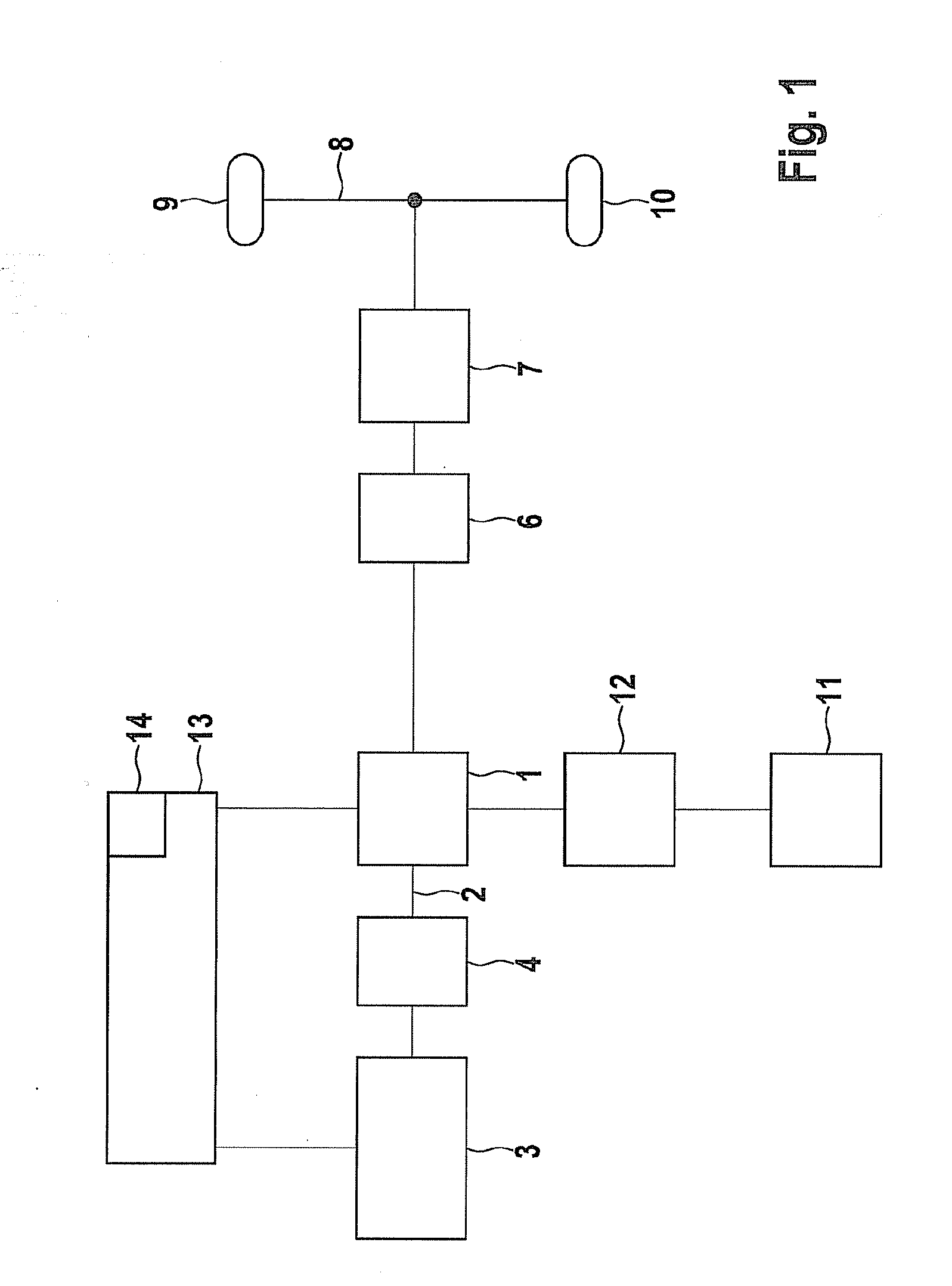
[0028]FIG. 1 shows a hybrid vehicle configured as a parallel hybrid. In this embodiment, an electric motor 1 is situated on drive shaft 2 of an internal combustion engine 3. Combustion engine 3 is connected to electric motor 1 by a separating clutch 4. Electric motor 1 leads to a power take-up element 6, which is connected to a transmission 7. Transmission 7 leads to an axle 8, on which the wheels 9, 10 are situated that are driven by the described power train.

[0029]Electric motor 1 is powered by a high-voltage battery 11, which is connected to electric motor 1 via an inverter 12. Electric motor 1 and combustion engine 3 are controlled by a control unit 13. Control unit 13 includes a memory 14, in which characteristic curves for different operating parameters are stored.

[0030]There are various operating modes, in which a parallel hybrid may be operated. A first operating mode, in which separating clutch 4 is open and combustion engine 3 is disconnected from the power train and autom...


PUM


Abstract

In a method for leak testing in an automated electrohydraulic clutch system in a motor vehicle, in which an electromechanical actuator controls the clutch travel of a clutch via a hydraulic piping system, in order that a defective system is detected reliably and rapidly, the leak in the clutch system is detected using a pressure measurement in the electromechanical actuator and compared to a characteristic clutch curve.

Description

CROSS-REFERENCE TO RELATED APPLICATIONS[0001]The present application is the national stage entry of International Patent Application No. PCT / EP2010 / 068608, filed on Dec. 1, 2010, and claims priority to Application No. DE 10 2009 055 161.1, filed in the Federal Republic of Germany on Dec. 22, 2009.FIELD OF INVENTION[0002]The present invention relates to a method for leak testing in an automated electrohydraulic clutch system in a motor vehicle, in which an electromechanical actuator controls the clutch travel of a clutch via a hydraulic piping system, and a device for implementing the method.BACKGROUND INFORMATION[0003]In automatic clutch systems, the disengagement travel at the clutch disk is determined; the friction torque at the clutch being controlled using this disengagement travel. In this context, the clutch is operated by an electromechanical actuator, which is controlled by a control unit, and whose forces are hydraulically transmitted to the clutch. To directly determine th...

Claims


Application Information

Patent Timeline
Patent Type & Authority Applications(United States)
IPC IPC(8): G01M3/28
CPCF16D48/066F16D2500/1024F16D2500/3024G01M3/26F16D2500/511F16D2500/70217F16D2500/70235F16D2500/3166
Inventor KLYMENKO, MYKHAYLOSCHNITZER, MANUELSCHENK, RENESCHMOLL GENANNT EISENWERTH, KASPAR
Owner ROBERT BOSCH GMBH
Why Eureka
Try Eureka