Method of forming electromechanical transducer film, electromechanical transducer film, electromechanical transducer element, and liquid discharge head

Active Publication Date: 2012-12-13
RICOH KK
View PDF0 Cites 15 Cited by
  • Summary
  • Abstract
  • Description
  • Claims
  • Application Information

AI Technical Summary

Benefits of technology

[0014]The embodiments of the present invention have been developed in view of the above problems. Objectives of the embodiments are to provide an electromechanical transducer film in which less cracks may occur; an electromechanical transducer element with a stable electrical characteristic; a liquid discharge head having a stable ink droplet discharging characteristic; and an image forming device including the liquid discharge head that can form high-quality images.
[0021]According to the embodiments, a novel method of forming the electromechanical transducer film, a novel electromechanical transducer film, a novel electromechanical transducer element, a novel liquid discharge head, and a novel image forming device having the liquid discharge head can be realized and provided. With these, the above objectives can be achieved. Namely, according to the embodiments, in the application process, the droplets of the sol-gel solution applied by the inkjet method are adhered to both inside the area of the desired pattern corresponding to the hydrophilic area and outside the area of the desired pattern corresponding to the hydrophobic area. Here, the surfaces of the hydrophilic area and the hydrophobic area are modified by the surface modification process. Among the droplets of the sol-gel solution adhered to, the droplets adhered to outside the area of the desired pattern are attracted toward inside the area of the desired pattern, and the droplets are leveled inside the desired pattern to be formed. Therefore, when the electromechanical transducer film is formed of the sol-gel solution through the drying process, the thermal decomposition process, and the crystallization process, the film thickness becomes even and the cracks are prevented from occurring. Therefore, the electric characteristic of the electromechanical transducer element formed of the film is stable. Further, since the electric characteristic of the electromechanical transducer element is stable, an ink discharging failure in the ink discharge head including the electromechanical transducer element is prevented from occurring. Therefore, the ink discharging characteristic of the ink discharging head is stabilized, and the quality of the images formed by the image forming device including the ink discharging head is improved.

Problems solved by technology

The dry etching is not easily applied to a metal composite oxide, especially to the PZT.
Such a method results in a higher cost.
Further, it is difficult to improve the selectivity between such a material and the lower electrode film.
Especially, for a substrate having a large surface area, nonuniformity in the etching rate can be a major obstacle for forming a film.
However, such an attempt has not been made, with a few exceptions.
Therefore, it becomes difficult to control the positions where the sol-gel solution droplets are adhered to, and it becomes difficult to form a desired pattern.
Therefore, many defects may be formed on the surface of the metal that forms the first electrode, and consequently stability becomes insufficient as an electromechanical transducer element.
On the other hand, even if the sol-gel solution droplets, whose sizes have been reduced, are adhered to inside the area of the desired pattern, since the amount of the solution is small, it is difficult to ensure a large area, which includes the position where the sol-gel solution droplet has been adhered to, for leveling the sol-gel solution on the surface of the metal that forms the first electrode, even though the surface of the metal is highly hydrophilic.
Furthermore, since the film thickness on the surface may become uneven, cracks tend to occur.
In addition, because of the unevenness of the generated film, the electrical characteristic of the electromechanical element formed of the film may be insufficient.

Method used


Image

  • Method of forming electromechanical transducer film, electromechanical transducer film, electromechanical transducer element, and liquid discharge head
  • Method of forming electromechanical transducer film, electromechanical transducer film, electromechanical transducer element, and liquid discharge head
  • Method of forming electromechanical transducer film, electromechanical transducer film, electromechanical transducer element, and liquid discharge head

Examples


first embodiment

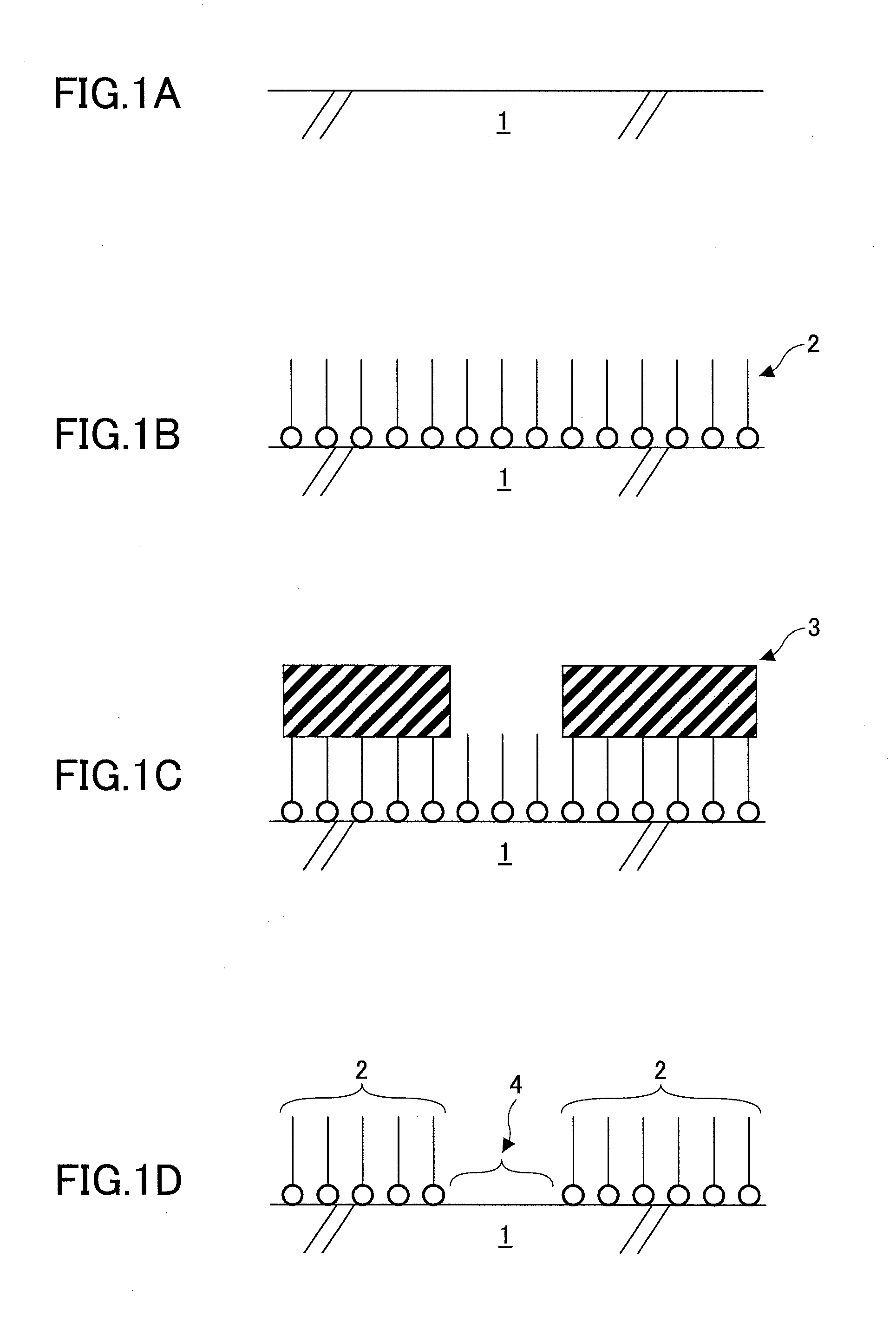
[0049]Hereinafter, the first embodiment of the method of forming the electromechanical transducer film by the sol-gel method is explained. FIGS. 1A-1D are schematic cross-sectional views illustrating the surface modification process for modifying the portion of the surface of a substrate 1. An electrode formed of platinum (Pt) (not shown) is formed as the first electrode or the lower electrode on the substrate 1 shown in FIG. 1A. FIG. 1B shows a state in which a SAM film 2 is formed on the whole surface of the substrate 1. The SAM film 2 is obtained by causing alkanethiol to be self-assembled by dipping the substrate 1 into an alkanethiol solution. Here, 1-dodecanethiol (CH3(CH2)11SH) is utilized. FIG. 1C shows a state in which photo resist layers 3 are pattern formed by photolithography, so as to remove a portion of the SAM film 2 placed at a position where the PZT precursor film is to be formed, and to protect a necessary portion of the SAM film 2. In the state shown in FIG. 1C, f...

second embodiment

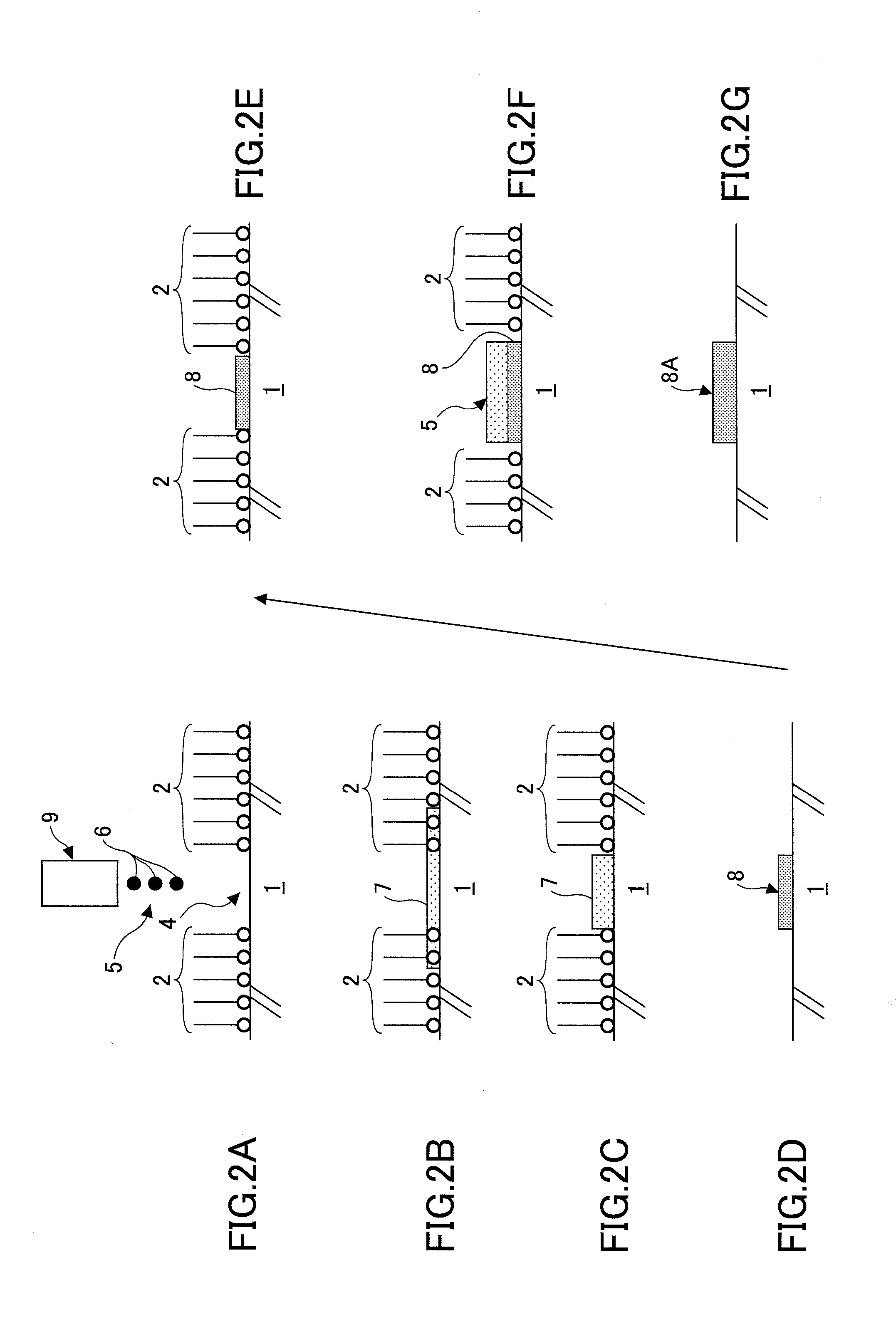
[0055]In a second embodiment, the PZT precursor solution 5 (sol-gel solution) is applied for the second time and after, similar to the method of forming the electromechanical transducer film according to the first embodiment. As it is shown in the example of FIG. 3A in which the PZT precursor solution 5 is applied for the second time, the PZT precursor solution 5 is applied to the substrate 1, so that the liquid droplets 6 of the PZT precursor solution 5 are adhered to specific portions of the desired pattern area (hydrophilic area 4), and that the center of each of the dots of the liquid droplets 6 is adhered to the center of the desired pattern area in the width direction. Here, the specific portions of the desired pattern area are the portions where the liquid droplets 6 have not been adhered to in the first time of the application. The portions of the liquid droplets 6 which have been adhered to the areas outside the desired pattern area are attracted toward inside the desired p...

third embodiment

[0057]In a third embodiment, as a continuation and repetition process of the process of the second embodiment, the substrate 1 was rinsed with isopropyl alcohol and dipped into an alkanethiol solution. In this manner, the SAM film 2 was formed. Since the SAM film 2 was not formed on the oxide film on and after the second time, the pattern of the SAM film 2 was obtained without performing the photolithography process, as shown in FIG. 2E. The contact angle of pure water with respect to the SAM film 2 was 110 degrees, and the contact angle of pure water with respect to the PZT film 8 was 18 degrees. In this state, the target position was aligned to the position of the PZT film 8, which was formed when the application process was performed for the first time, and the PZT precursor solution (sol-gel solution) 5 was applied again to the substrate 1 by the method according to the first embodiment and the second embodiment using the inkjet application device. Similar to the cases of the fi...


PUM


Abstract

Disclosed is an electromechanical transducer film forming method including a surface modification process; an application process; and processes of drying, thermally decomposing, and crystallizing sol-gel solution applied to a portion of a surface of a first electrode. An electromechanical transducer film is formed on a desired pattern area on the surface of the first electrode by repeating the above processes. In the application process, each of dots of the sol-gel solution applied by the inkjet method drops onto both a first area inside the desired pattern area and a second area outside the desired pattern area. The first area is a hydrophilic area on the surface of the first electrode, and the second area is a hydrophobic area on the surface of the first electrode. The hydrophilic area and the hydrophobic area have been modified by the surface modification process.

Description

BACKGROUND OF THE INVENTION[0001]1. Field of the Invention[0002]Embodiments of the present invention relate to a method of forming an electromechanical transducer film, the electromechanical transducer film, an electromechanical transducer element, a liquid discharge head, and an image forming device. Specifically, the embodiments of the present invention relate to an electromechanical transducer element, an electromechanical transducer film included in the electromechanical transducer element, and a method of forming the electromechanical transducer film that are utilized as a piezoelectric element of a liquid discharge head included in an inkjet recording device; a printing machine, such as a printer, a facsimile machine, a copier, a plotter, and a screen printing machine; or a combined machine having the functions of these devices.[0003]2. Description of the Related Art[0004]In an inkjet recording device which is utilized as an image recording device, such as a printer, a facsimi...

Claims


Application Information

Patent Timeline
IPC IPC(8): B41J2/045H01L41/22H01L41/318H01L41/39
CPCB41J2/161H01L41/047B41J2/14201B41J2/164H10N30/081H10N30/078H10N30/87
Inventor SHIMOFUKU, AKIRAMACHIDA, OSAMUTASHIRO, RYOHWATANABE, YASUHIRO
Owner RICOH KK
Why Eureka
Try Eureka