
Laser delivery system for eye surgery

a laser delivery system and delivery system technology, applied in laser surgery, medical science, surgery, etc., can solve the problems of inability to achieve a high enough fluence for breakdown by increasing the laser pulse energy, unsatisfactory way of achieving a high enough fluence for breakdown, and large shock wave considered an undesired side effect, etc., to achieve the effect of increasing the 3 dimensional scanning ability of the delivery system

Active Publication Date: 2012-12-13
LENSAR LLC
View PDF9 Cites 37 Cited by
  • Summary
  • Abstract
  • Description
  • Claims
  • Application Information

AI Technical Summary

Benefits of technology

[0025]A novel aspect of the various embodiments of the invention includes the use of a scanning system, that leaves the focusing lens (assembly) always under a normal (90 degrees) optical incidence angle and therefore dramatically minimizes optical aberrations, that normally require complex optical lens systems to compensate. This design approach allows for the use of a very simple and small main focusing lens (assembly). The various embodiments of the invention allow for no contact between the laser delivery system and the eye.
[0031]In some embodiments this 45° mirror becomes a two axis scanning mirror that increases the 3 dimensional scanning ability of the delivery system.

Problems solved by technology

The precision and quality of these methods is limited.
The way of achieving a high enough fluence for breakdown by increasing the laser pulse energy is less desirable since a higher pulse energy comes with a larger cavitation bubble and associated shock wave.
Furthermore a large shock wave is considered a undesired side effect since it has the potential to damage surrounding tissues.
The laser delivery systems for such laser parameters face several challenges due to the high numerical aperture required for to achieve a very small spot size.
These systems get further complicated by using a laser beam that is scanned through the focusing lens assembly.
Placement of this patient interface adds significant complexity to the surgical setup and can cause undesired or harmful high intraocular pressures levels for the duration of the laser procedure.
The patient interface is typically provided sterile and is used only once therefore adding significant cost to the overall cataract procedure.
Additionally, No current patient interface or laser delivery system that can perform the laser cornea incisions and laser capsulotomy is compatible or has been integrated with a standard surgical microscope.
This causes a significant time delay and logistical effort.

Method used


Image

  • Laser delivery system for eye surgery
  • Laser delivery system for eye surgery
  • Laser delivery system for eye surgery

Examples


Embodiment Construction

[0057]The invention described relates to techniques apparatus, and systems for laser eye surgery or laser assisted eye surgery. Specifically described herein are methods and systems for delivering a focused femtosecond laser beam into the eye of a patient.

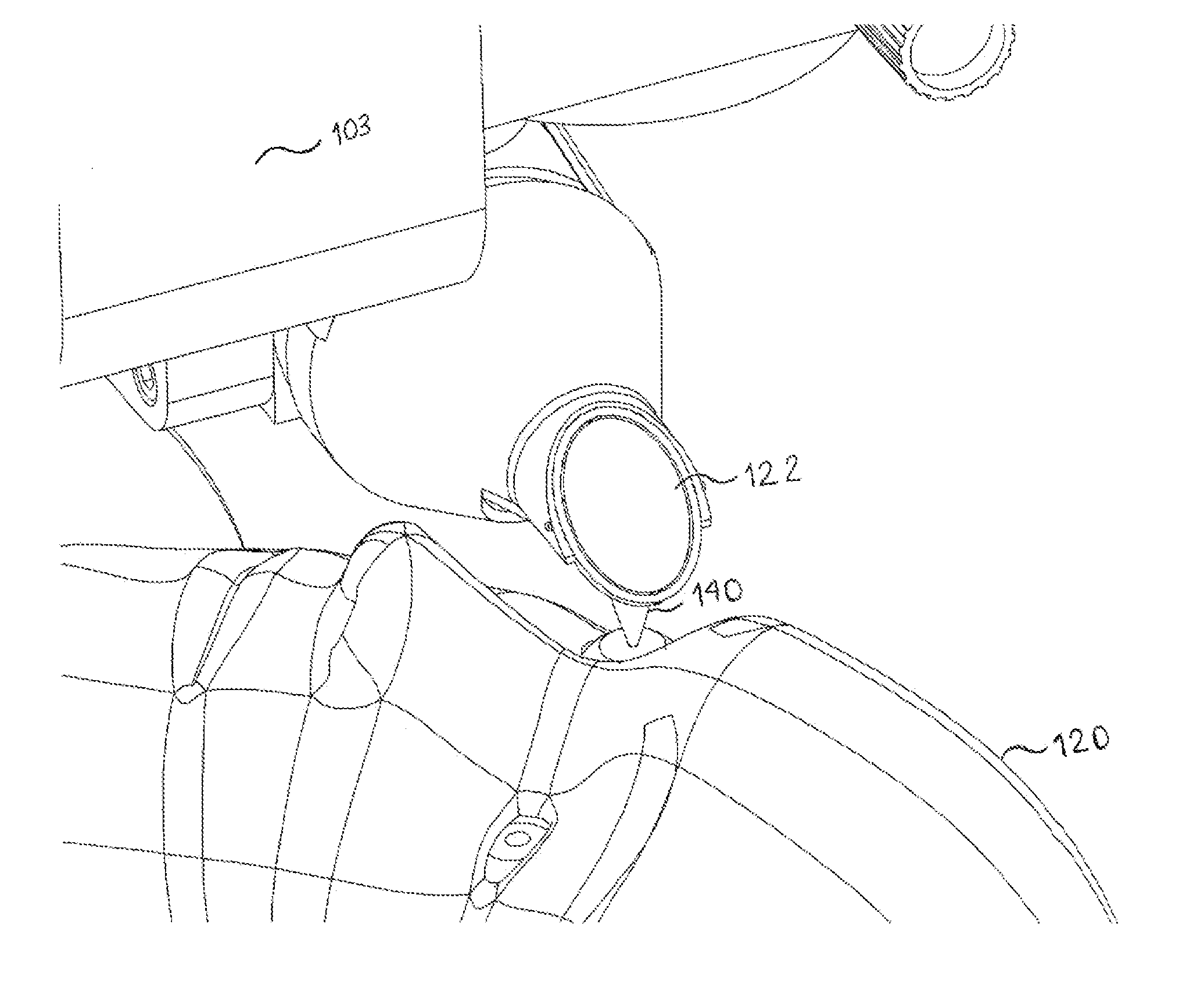
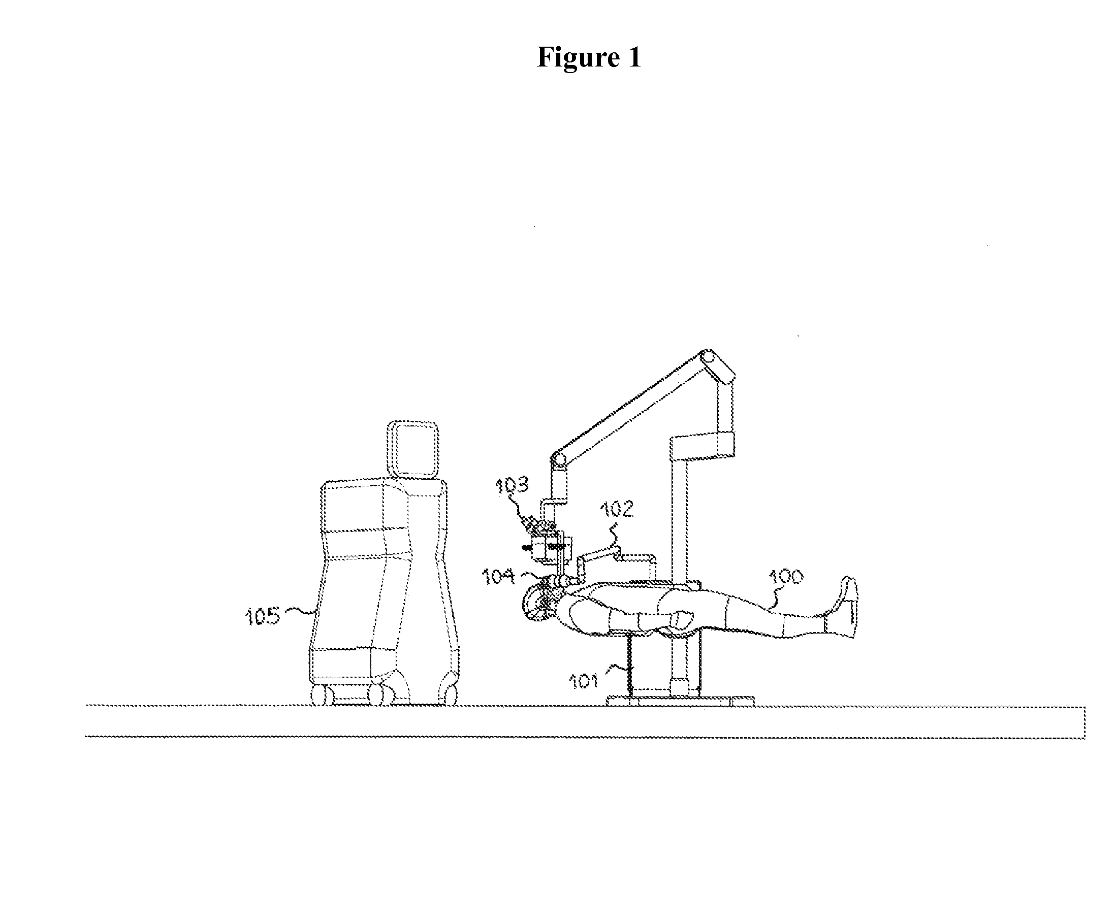
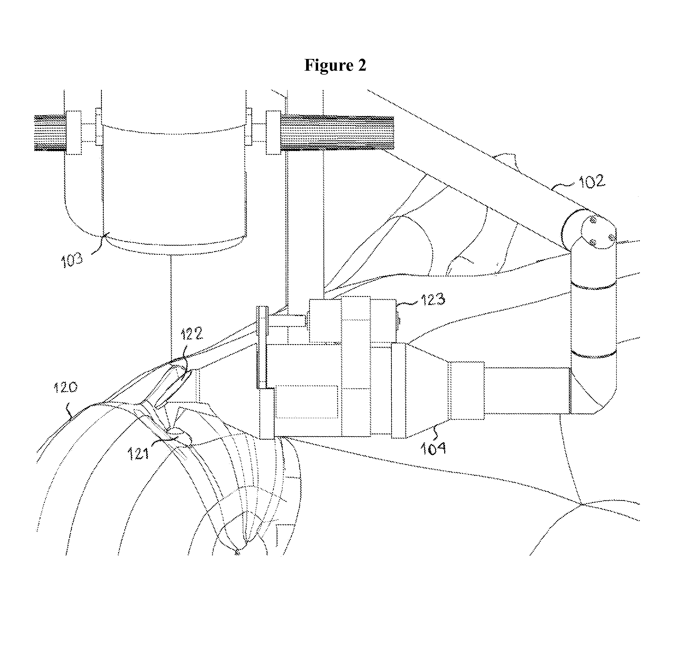
[0058]An exemplary embodiment of the invention is shown in FIG. 1. FIG. 1 shows a system overview of the laser delivery system optics (104) integrated into a typical ophthalmic surgical microscope 103. The delivery system optics unit 104 connects to the laser engine 101 that is placed here next to the microscope stand through an articulating arm 102 that allows propagation of a laser beam. The patient 100 lays in a standard position typical for cataract surgery. The overview is completed by illustrating a typical size phacoemulsification machine 105 close to the surgical microscope. A closer view of this exemplary embodiment is shown in FIG. 2. This view shows the right eye being treated. The left eye is treated by moving the deliv...


PUM


Abstract

A photodisruptive laser delivery system and method for use in eye surgery. The photo disruptive laser delivered in pulses in the range of <10000 femtoseconds, used to create incisions in eye tissue is delivered by novel means to minimize optical aberrations without the use of a complex system of multiply precisely arranged lenses. This novel means include a scanning design that allows the focusing lens to always remain under normal incidence to the photodisruptive laser beam, negating the need for overly complex aberration correction set up. The focusing lens is configured to move within a surrounding beam to facilitate two dimensional controls over the treatment space. Controlling beam divergence prior to focusing allows for 3D incisions. The system and methods of use accomplish precise treatment without the need to contact the patient and can be integrated into standard surgical microscopes to improve operational efficiency and hospital workflow.

Description

CROSS-REFERENCE[0001]The present application is a non-provisional of, and claims the benefit of priority under 35 U.S.C. §119(e) of U.S. Provisional Application No. 61 / 495,370 filed Jun. 9, 2011, the entire contents of which are incorporated herein by reference.[0002]The present application is related to the following co-pending patent application U.S. 61 / 619,386 the entire contents of which are incorporated herein by reference. The pending application is also related to U.S. patent application Ser. No. 12 / 902,105 and PCT / US11 / 54506.BACKGROUND OF THE INVENTION[0003]The present invention generally relates to systems, apparatus, and methods related to eye surgery. More particularly, the present invention relates to systems, apparatus and methods for cataract surgery. Cataract surgery is one of the most common ophthalmic surgical procedures performed. The primary goal of cataract surgery is the removal of the defective lens and replacement with an artificial lens or intraocular lens (I...

Claims


Application Information

Patent Timeline
IPC IPC(8): A61F9/011A61F9/01
CPCA61F9/00825A61F2009/00889A61F2009/00887A61F2009/0087A61F2009/00897A61B90/50A61B18/20A61F9/008A61F9/00804A61F9/00821A61F2009/00872A61F9/00745
Inventor HORVATH, CHRISTOPHERVERA, VANESSA ISABELLA
Owner LENSAR LLC
Learn More