Hybrid solar collector

Active Publication Date: 2012-12-20
NAKED ENERGY
View PDF11 Cites 11 Cited by
  • Summary
  • Abstract
  • Description
  • Claims
  • Application Information

AI Technical Summary

Benefits of technology

[0171]Preferably, the temperature control element is arranged to control the temperature of the photovoltaic elem

Problems solved by technology

Such hybrid devices have been found to suffer from the problem that the elements of the photovoltaic array become hot when the device is operating.
Also, in general, photovoltaic elements subject to high temperatures may s

Method used


Image

  • Hybrid solar collector
  • Hybrid solar collector
  • Hybrid solar collector

Examples


first embodiment

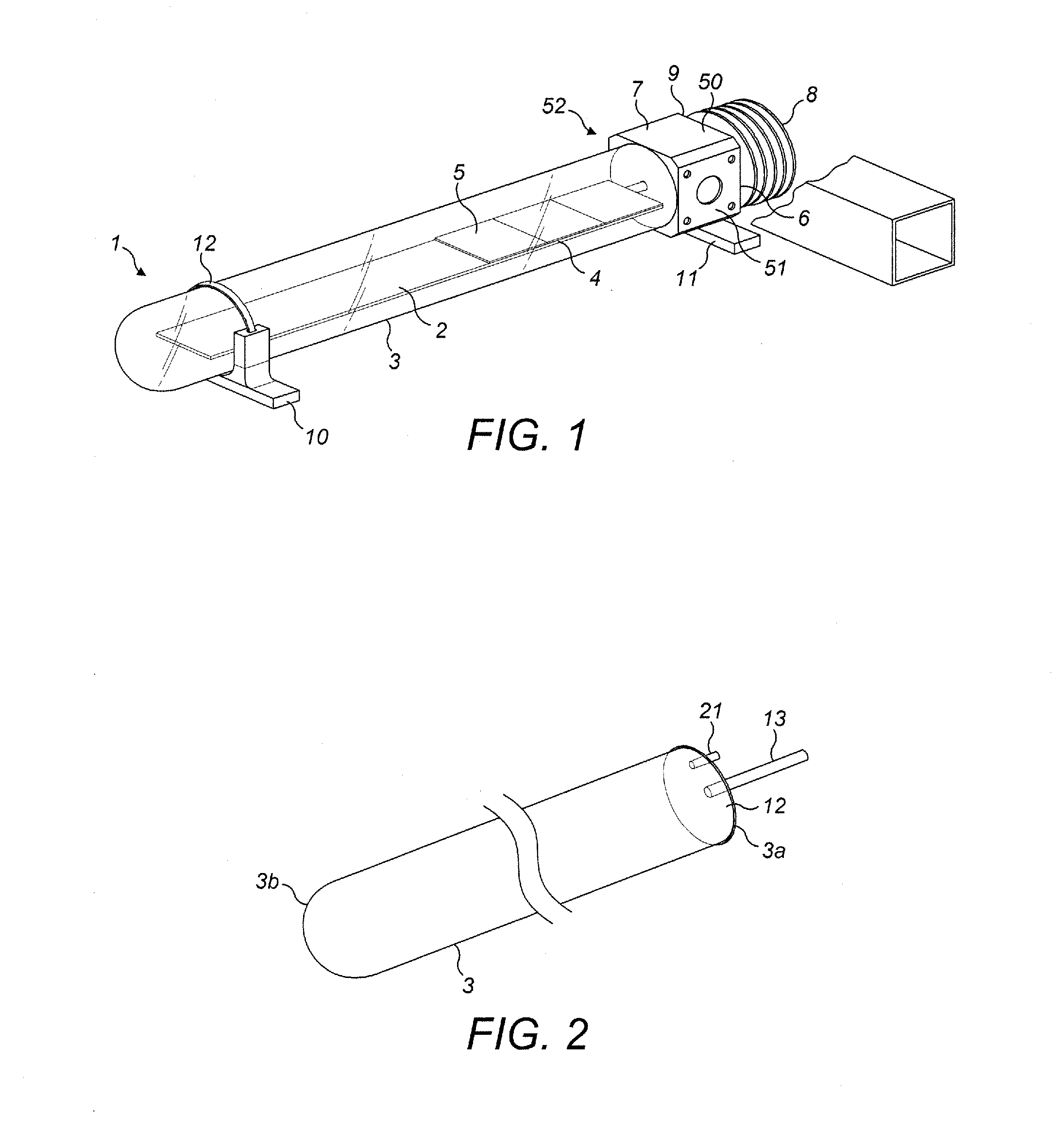
[0357]Apparatus according to a first embodiment of the present invention is illustrated in FIG. 1. FIG. 1 shows a general exterior view of a first embodiment of a hybrid solar energy converter 1 according to the present invention.

Overview

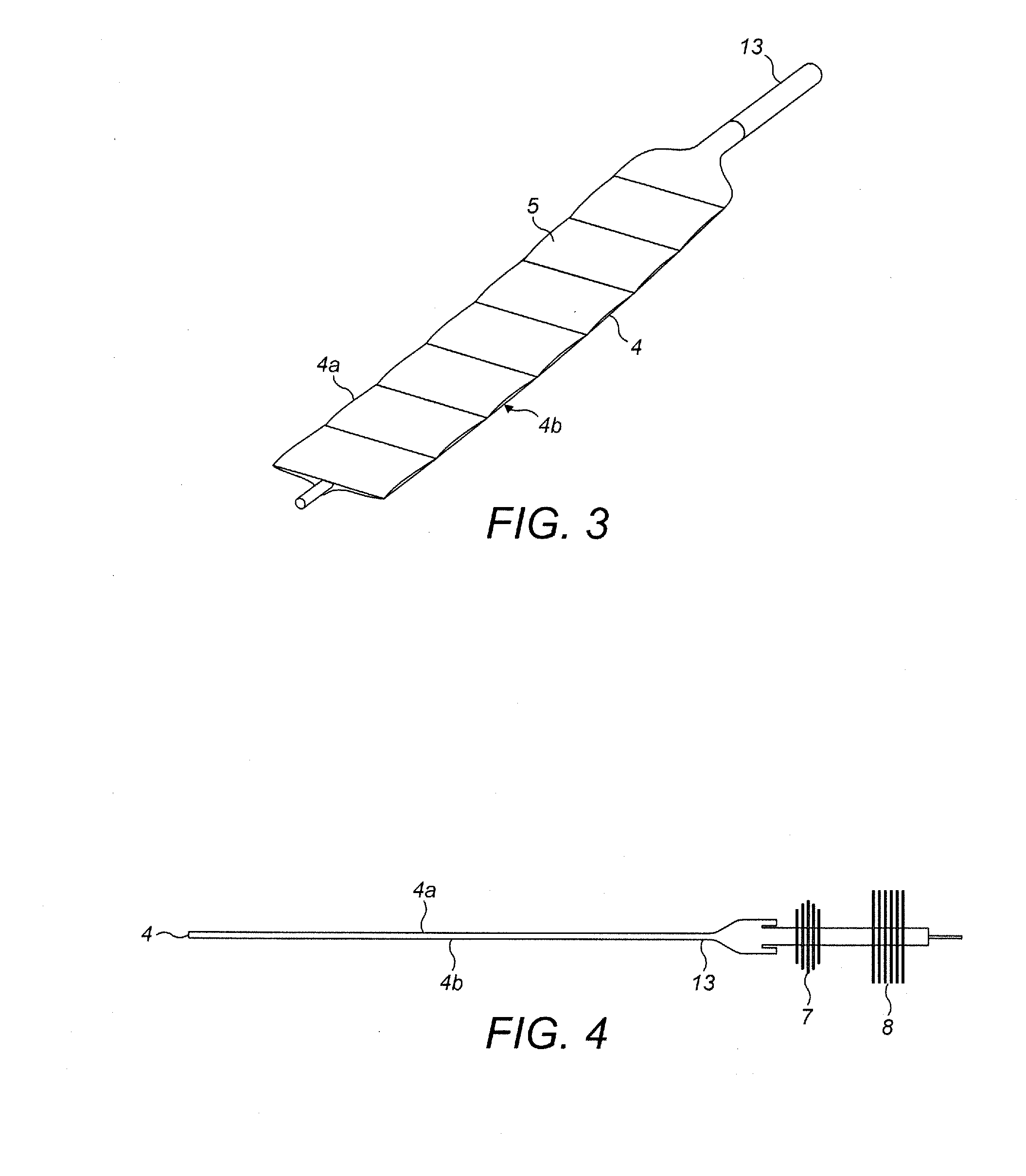
[0358]In the first embodiment, the hybrid solar energy converter 1 includes a solar energy collector assembly 2 housed within a sealed transparent tube 3. The solar energy collector assembly 2 includes a heat transport element 4 and an array of photovoltaic elements 5 mounted on an upper surface of the heat transport element 4. The hybrid solar energy converter 1 also includes a heat exchange assembly 6 at one end of the transparent tube 3. One end of the solar energy collector assembly 2 is connected to the heat exchange assembly 6. In one example the photovoltaic elements 5 may be formed of silicon. In another example the photovoltaic elements 5 may be formed of gallium arsenide. In other examples, photovoltaic elements formed of other semiconduct...

second embodiment

[0476]Apparatus according to a second embodiment of the present invention is illustrated in FIG. 10. FIG. 10 shows a general exterior view of a second embodiment of a hybrid solar energy converter 101 according to the present invention.

Overview

[0477]In the second embodiment, the hybrid solar energy converter 101 includes a solar energy collector assembly 102 housed within a sealed transparent tube 103. The solar energy collector assembly 102 includes a heat transport element 104 and an array of photovoltaic elements 105 mounted on an upper surface of the heat transport element 104. The hybrid solar energy converter 101 also includes a heat exchange assembly 106 at one end of the transparent tube 103. One end of the solar energy collector assembly 102 is connected to the heat exchange assembly 106. Similarly to the first embodiment, in different examples the photovoltaic elements 105 may be formed of silicon, or gallium arsenide, or other suitable semiconductor materials. In other ex...

third embodiment

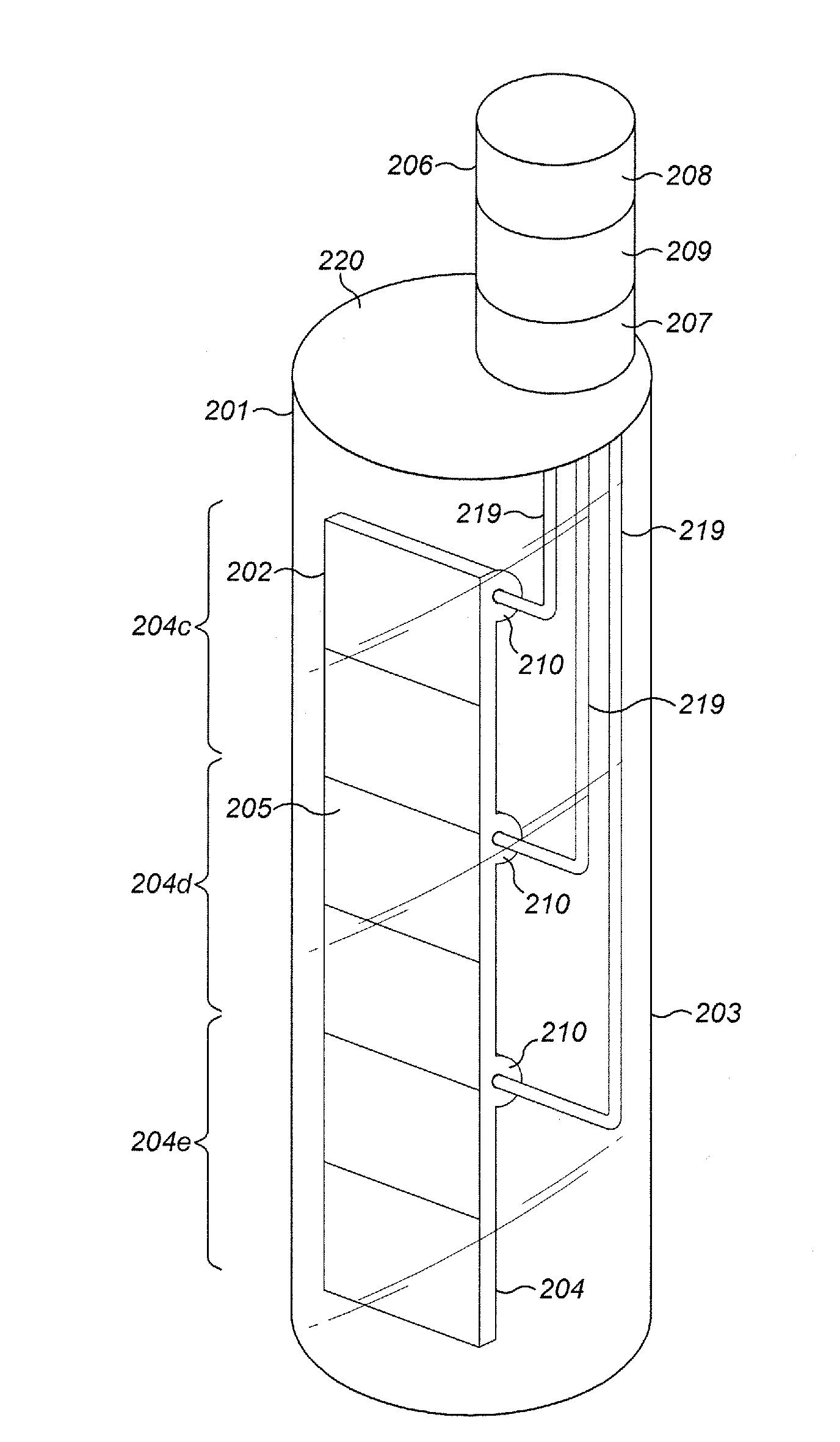
[0631]Apparatus according to a third embodiment of the present invention is illustrated in FIG. 20. FIG. 20 shows a general exterior view of a third embodiment of a hybrid solar energy converter 201 according to the present invention.

Overview

[0632]In the third embodiment, the hybrid solar energy converter 201 includes a solar energy collector assembly 202 housed within a sealed transparent tube 203. The solar energy collector assembly 202 includes a heat transport element 204 and an array of photovoltaic elements 205 mounted on an front surface of the heat transport element 204, the front surface being the surface exposed to incident solar radiation in use. The hybrid solar energy converter 201 also includes a heat exchange assembly 206 at one end of the transparent tube 203. One end of the solar energy collector assembly 202 is connected to the heat exchange assembly 206. Similarly to the first and second embodiments, in different examples the photovoltaic elements 205 may be forme...


PUM


Abstract

A solar energy converter comprising: a solar energy absorber, the solar energy absorber comprising a photovoltaic element; a heat transfer element in thermal contact with the solar energy absorber; a primary heat exchanger in thermal contact with the heat transfer element; a secondary heat exchanger; and a heat transfer control element; wherein the heat transfer control element is arranged to selectively place the secondary heat exchanger either in thermal contact with the heat transfer element or out of thermal contact with the heat transfer element.

Description

RELATED APPLICATIONS[0001]This application is a U.S. Utility patent Application which claims priority to British patent Application No. GB 1104722.2, filed on Mar. 21, 2011, the entirety of which is herein incorporated by reference.FIELD OF THE INVENTION[0002]This invention relates to solar energy converter devices and in particular to devices which convert incident solar energy into heat and electricity.[0003]Devices converting solar energy into electricity are known. One means of converting solar energy into electricity is the use of photovoltaic arrays. Photovoltaic arrays generally consist of semi-conductor materials appropriately encapsulated, and arranged to generate electricity when exposed to solar radiation.[0004]Separately, devices converting solar energy into useable heat are known. A variety of thermal collection devices are known which absorb heat energy when exposed to solar radiation. These thermal collectors heat up as they absorb heat energy from solar radiation and...

Claims


Application Information

Patent Timeline
IPC IPC(8): H01L31/058F24S10/40F24S10/95
CPCF24J2/055H02S40/44F24J2/4621F28D15/0233H01L31/0521Y02B10/12F28F13/187F28D15/0266Y02B10/14Y02B10/22Y02E10/44Y02B10/70Y02E10/60Y02E10/52F24J2/32F24S10/45F24S40/50F24S10/95Y02E10/547Y02B10/20Y02B10/10F24S10/90H01L31/052F24S40/55F24S10/40F24S50/40F28D15/02Y02E10/50
Inventor BOYLE, RICHARDWILLIAMS, CHRISTOPHECOTTINGTON, NORMAN
Owner NAKED ENERGY
Why Eureka
Try Eureka