Method and apparatus for handling material in a pneumatic materials handling system

a technology of pneumatic materials and handling systems, applied in the field of material handling systems, can solve the problems of high energy consumption of drive devices, high cost of drive devices, blade breakage, etc., and achieve the effect of efficient compacting, efficient solution, and efficient fitting

Active Publication Date: 2012-12-20
MARICAP OY
View PDF4 Cites 6 Cited by
  • Summary
  • Abstract
  • Description
  • Claims
  • Application Information

AI Technical Summary

Benefits of technology

[0014]The solution according to the invention has a number of important advantages. By means of the invention a particularly efficient solution for the handling of material, more particularly for pneumatic pipe transport, is achieved. With the solution according to the invention the material to be handled is made to be centered, i.e. is brought towards the center, in which case the material can be efficiently fitted into a transport pipe or a container. More particularly, waste material can with the solution according to the invention be efficiently compacted with the rotary shaper according to the invention and efficient transportation can be achieved with a significantly smaller pipe size compared to unshaped waste material. By using suction, in addition to gravity, to transfer the material to be handled from the rotary shaper into the transport pipe, an advantageous solution for a combination of a rotary shaper and pipe transport is achieved. By forming the output aperture of the rotary shaper to be to some extent smaller than the cross-sectional area of the transport pipe, effective transfer of the handled material into the transport pipe by means of suction can be achieved. By forming the output aperture into a shape that deviates from a circle, e.g. into an oval or elliptical shape, such that the smallest diameter of the output aperture is smaller than the diameter of the transfer pipe and the largest diameter corresponds to the diameter of the transfer pipe, efficient transfer of replacement air can be achieved past the material to be handled and into the transfer pipe. By forming the shape of the aperture of the handling means, an extremely efficient shaping of the material to be handled for onward transportation can be achieved. With a certain magnitude of the angle between the edges of the apertures of consecutive handling means, effective operation of the apparatus is achieved. Further, it can be advantageous to bring about an air current by directing at least a part of the replacement air via the medium ducts and / or from between the handling means such that in suction the seals admit inward air. In this case the air assists the transfer of the material to be handled in the rotary shaper towards the output aperture and onwards into the output aperture. Replacement air can be brought into the rotary shaper e.g. in a corresponding manner to what has been done in connection with refuse chutes, e.g. by applying the solution of publication WO / 2009 / 13037 in connection with the rotary shaper.

Problems solved by technology

In the solution according to the publication large output powers are typically needed, especially in situations in which the device is used to cut or fine-grind a material, in which case the energy consumption of the drive devices and the costs of the drive devices are high.
In addition, the passage of stones and metals or other corresponding material between the cutting blades can produce breakage of the blades.

Method used


Image

  • Method and apparatus for handling material in a pneumatic materials handling system
  • Method and apparatus for handling material in a pneumatic materials handling system
  • Method and apparatus for handling material in a pneumatic materials handling system

Examples


Embodiment Construction

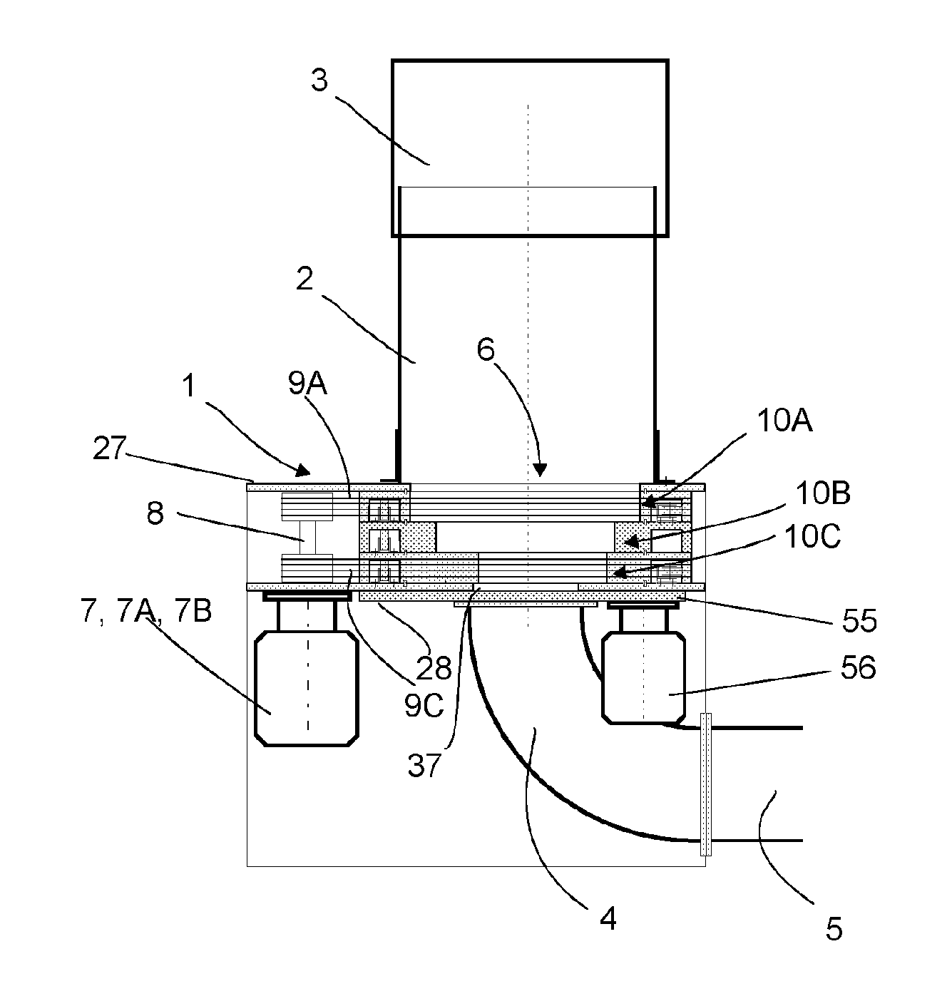
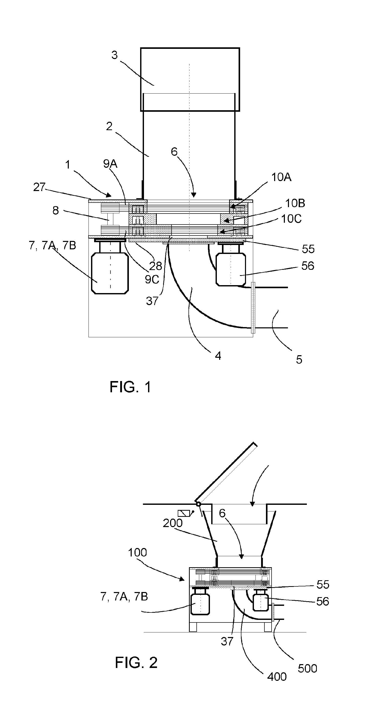
[0028]FIG. 1 presents one embodiment of the solution according to the invention, in which the rotary shaper device 1 is arranged in connection with a refuse chute 3 or corresponding with a fitting part 2. Only a part of the refuse chute is presented. The material, such as household waste, waste paper, cardboard or other waste, is input into a refuse chute 3 and from there onwards, via a fitting part 2, into an input aperture 6 of the rotary shaper 1. The material to be handled is shaped and compacted in the rotary shaper and after handling is conducted via an output coupling 4 into transfer piping 5 by means of suction and / or a pressure difference produced by e.g. the drive devices of a pneumatic pipe transport system. One advantage of the embodiment of the invention is that the waste material is made into a suitable shape, in which it fits for transferring in transport piping 4, 5. In this case transfer piping 5 that is significantly smaller in diameter can be used. According to on...


PUM

PropertyMeasurementUnit
diameteraaaaaaaaaa
diameteraaaaaaaaaa
diameteraaaaaaaaaa

Abstract

Method for handling material in a pneumatic materials handling system, in which material is input from an input aperture of an input point and is handled with a shaping device, arranged in connection with the input point or in the proximity of it, to be more compact and is transferred onwards, which shaping device is a rotary shaper, which includes a rotatable handling device, which includes an aperture, which is arranged eccentrically with respect to the axis of rotation, and which rotary shaper includes at least one stationary handling device, in which case the material to be handled is conducted into the rotary shaper and / or through it at least partly by means of gravity. The material to be handled is conducted into the rotary shaper and / or through it at least partly by means of suction and / or a pressure difference.

Description

BACKGROUND OF THE INVENTION[0001]The object of the invention is a method as defined in the preamble of claim 1.[0002]The object of the invention is also an apparatus as defined in the preamble of claim 17.[0003]The invention relates generally to materials handling systems, such as partial-vacuum conveying systems, more particularly to the collection and moving of wastes, such as to the moving of household wastes.[0004]Systems wherein wastes are moved in piping by means of an air current produced by a pressure difference and / or suction are known in the art. In these, wastes are moved long distances in the piping. It is typical to these systems that a partial-vacuum apparatus is used to bring about a pressure difference, in which apparatus a partial vacuum is achieved in the transfer pipe with partial-vacuum generators, such as with vacuum pumps or with an ejector apparatus. A transfer pipe typically comprises at least one valve means, by opening and closing which the replacement air ...

Claims


Application Information

Patent Timeline
Patent Type & Authority Applications(United States)
IPC IPC(8): B65F5/00
CPCB65F5/005B65G51/02B65G53/48B02C18/0084B30B3/04B30B9/3035B02C18/0092B30B13/00B30B15/30B65G53/16B65F5/00B65F2210/162B65F2210/188
Inventor SUNDHOLM, GORAN
Owner MARICAP OY
Why Eureka
Try Eureka