[0011]Besides the at least one electroacoustic transducer element, the transducer core is able to include further elements. In particular, as will be stated in greater detail below, the transducer core is able to include at least one matching element which is equipped to improve an acoustic
coupling between the electroacoustic transducer element and the fluid medium. In this context, it may be an impedance-matching element. In optimum fashion, this impedance-matching element has an
acoustic impedance which is between the
acoustic impedance of the electroacoustic transducer element and the
acoustic impedance of the fluid medium, ideally close to the geometric mean of these acoustic impedances. In the case of real ultrasonic transducers and especially in the case of gaseous media, matching elements are also used having other, mostly higher acoustic impedances. The matching element may also include a plurality of materials having different acoustic impedances and / or a material having an acoustic impedance gradient. For possible embodiments of such a matching element, which may be embodied, for example, as a matching layer, we may point out the documents cited above, namely, published German
patent application documents DE 10 2007 010 500 A1, DE 10 2007 037 088 A1 and DE 10 2008 055 126.0. The matching elements used in those documents may basically also be used within the scope of the present invention. Moreover, the transducer core may include additional elements. For example, between the optional matching element and the electroacoustic transducer element, at least one compensation element, particularly at least one compensation layer may be provided. Such a compensation element is able to prevent, for instance, the buildup of thermomechanical stresses based on different thermal coefficients of expansion of the electroacoustic transducer element and the matching element, for example, in that a
thermal coefficient of expansion is selected for this compensation element which lies between that of the electroacoustic transducer element and that of the matching element. As an example, this compensation element may include at least one
adhesive layer. However, other designs are basically also possible.
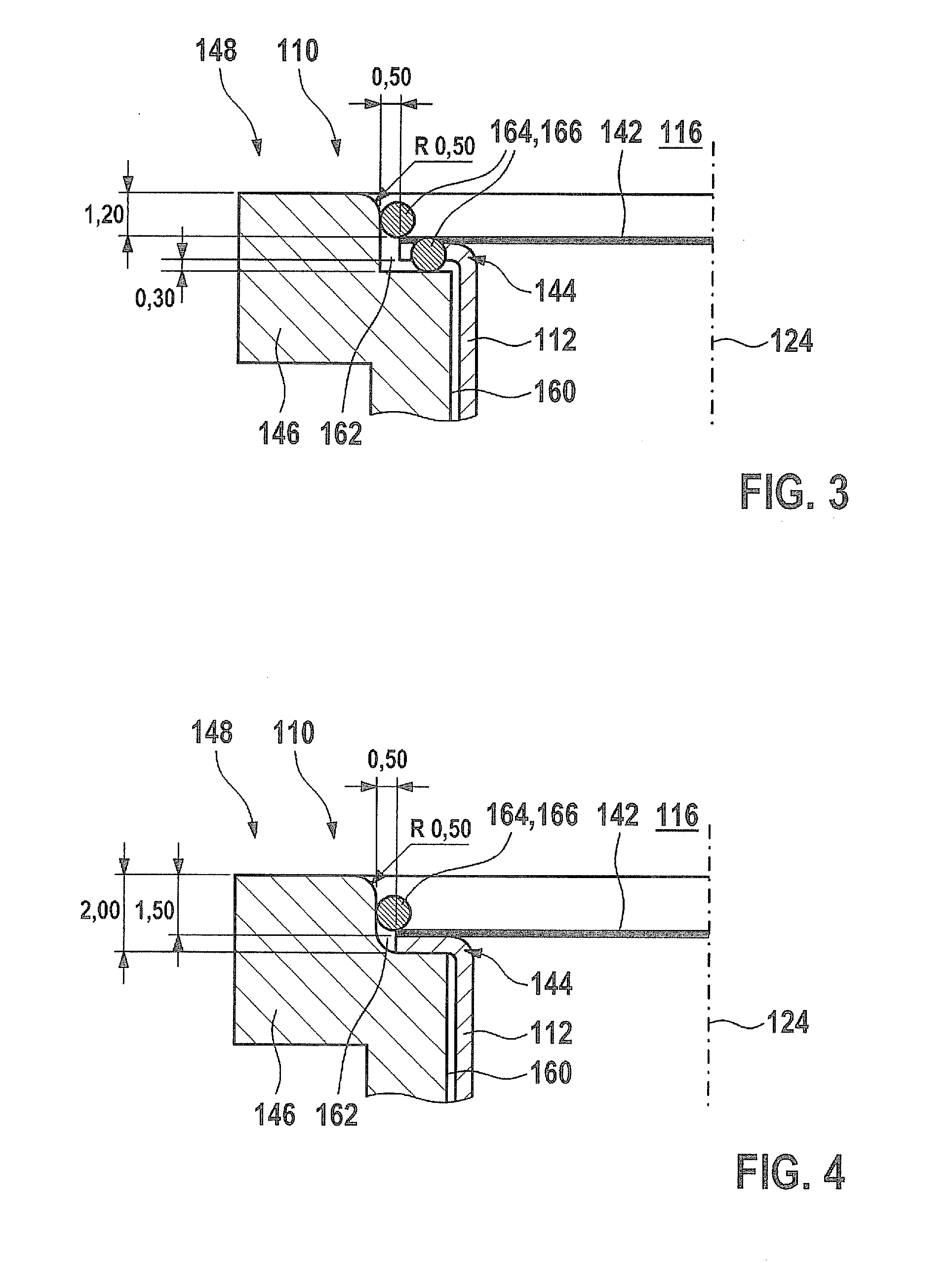
[0015]By a sealing material one should understand, in this context, basically any material which is able to be applied to the sealing foil in a deformable state, for instance, in a liquid, viscous or pasty or otherwise deformable state. The sealing foil is thus able to adapt itself to the shape of the edge of the foil. The sealing material is also able particularly to penetrate wholly or partially into an interstice between the housing and the edge of the sealing foil, and / or is able to close a gap between an edge of the sealing foil and the housing. By sealing, one should generally understand, in this context, a state in which the inner space is protected by the sealing material at least partially from influences of the fluid medium, such as from
chemical effects and / or pressure effects.
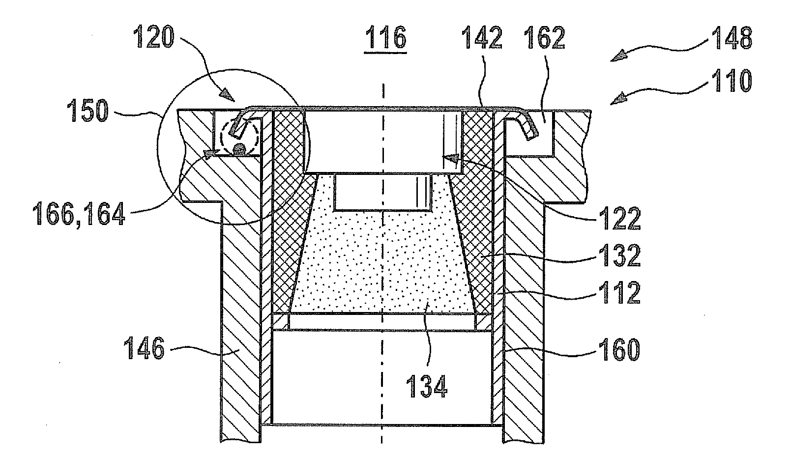
[0024]The ultrasonic transducer provided and the
sensor system provided have numerous advantages over the known ultrasonic transducers and sensor systems. In particular, an ultrasonic transducer impervious to media may be provided in this way which, in particular, may also be used for flow measuring in internal
combustion engines and / or in other aggressive environments. Without the sealing foil named and / or the sealing, the inner space of the ultrasonic transducer, for instance, damping or structure-borne
noise decoupling in the ultrasonic transducer, would be exposed to the, at times, aggressive fluid media, for instance, the media contained in a motor vehicle intake tract, such as
moisture, oil,
exhaust gas components, hydrocarbons, acids and similar aggressive media. For the decoupling of the transducer core from the housing, as a rule, soft silicones are required however, which have
low resistance to these media.
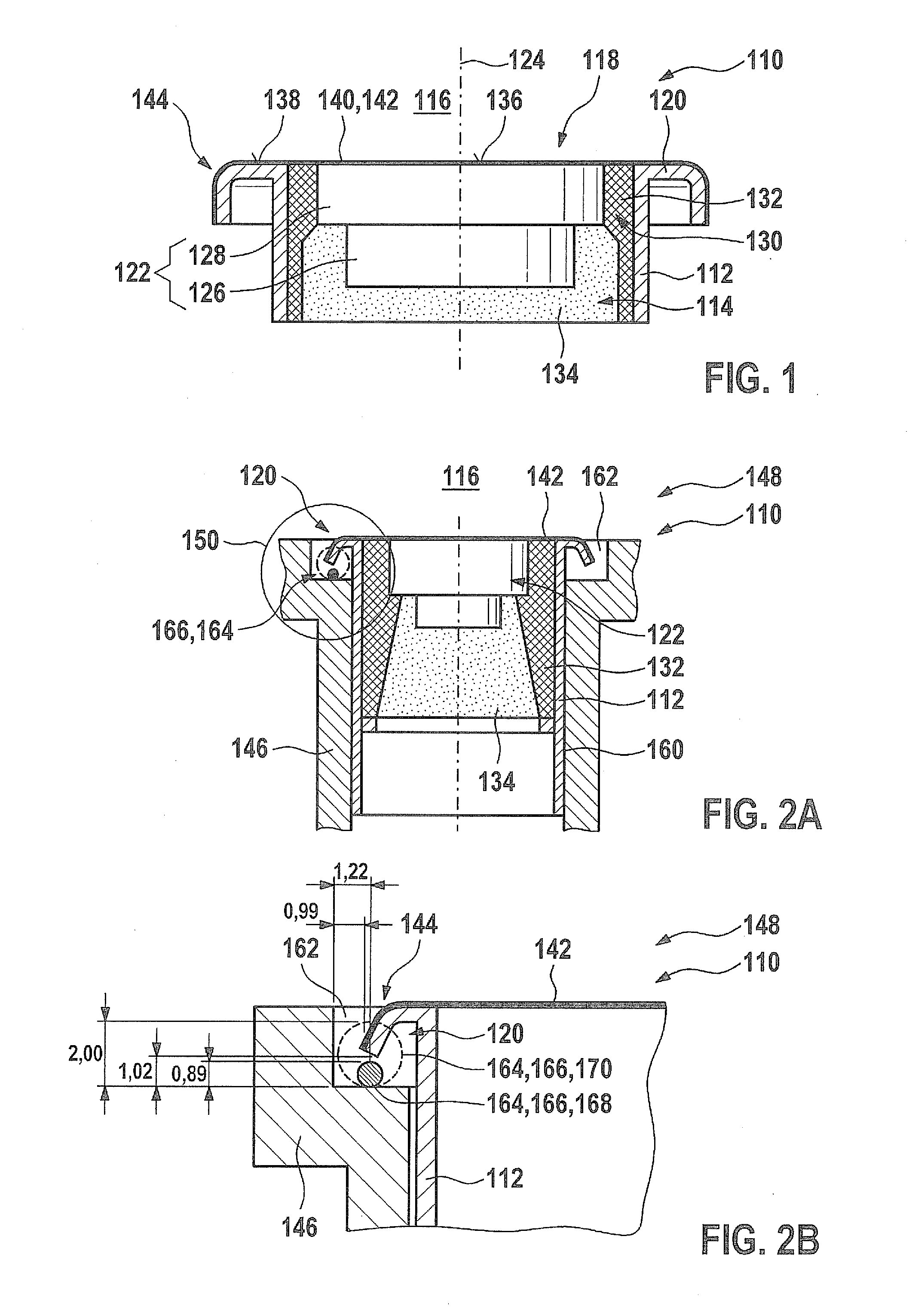
[0025]However, a sealing foil by itself is usually exposed to relatively high stresses, especially because of pressure and / or temperature fluctuations. These stresses may be particularly attributed to thermal expansions of materials in the ultrasonic transducer, such as
plastic materials. Accordingly, in the usual constructions, the sealing foil is easily infiltrated by media at its edges. On the other hand, by sealing the edges of the foil, the ultrasonic transducer is mechanically stabilized and with respect to its tightness.
[0026]Furthermore, producing the ultrasonic transducer named is also easily managed. The at least one sealing element may be used simultaneously for fastening the ultrasonic transducer in the sensor housing and / or for sealing the ultrasonic transducer from the sensor housing. The simultaneous production of the sealing and the fastening and / or seal considerably simplifies the process sequence during manufacturing.
