Green Power Converter

a power converter and green technology, applied in the direction of dc-dc conversion, dc-dc network circuit arrangement, efficient power electronics conversion, etc., can solve the problems of greying and dark world, traditional power conversion cannot be performed in order, etc., and achieve the reduction of circuit complexity, power consumption and failure rate of the whole power converter.

Inactive Publication Date: 2013-01-10
YU BAICHOU
View PDF5 Cites 77 Cited by
  • Summary
  • Abstract
  • Description
  • Claims
  • Application Information

AI Technical Summary

Benefits of technology

[0007]The invention omits the pulse width modulation (PWM) technique in the traditional power converter, no high-frequency power device exists in the main circuit, no EMI interference is generated, and meanwhile, the unit circuit, the amplitude height modulation circuit and the dynamic rectification circuit are adopted. Only a small part of the input power needs to undergo traditional power conversion so as to acquire the whole output power, namely that a large part of the output power neither need traditional power conversion nor need to pass through the magnetic core transformer. The input AC voltage neither needs to be rectified and filtered nor has large inductance and large capacitance, thus the power factor is 1, and the total harmonic distortion (THD) is 0. A transformer secondary side can acquire a DC circuit, and can also acquire an AC voltage by adopting dynamic rectification. The circuit complexity, the power consumption and the failure rate of the whole power converter are greatly reduced.
[0066]The dynamic adjustment has the result that the amplitude of the output voltage Vo only varies between the DC reference voltages V1, V2, and V1, V2 can be manually set in advance, i.e. the amplitude and the voltage-stabilized accuracy of the output voltage Vo can be manually set in advance. Here, the variation of R1 is quantized or digital in stead of continuous. The method is to divide the adjustable part of the resistor R1 into N equal parts, each equal part of R1 is connected with one digital switch in parallel, and the opening of the switches indicates that this equal part of resistor is connected or increased. The closing of the switches indicates that this equal part of resistor is short-circuit or decreased. The opening and closing of the switches are automatically controlled by the digital circuit, and the speed is very quick.
[0067]The amplitude height modulation circuit technique adopts the digital circuit to control the micro increment of the adjustable part of the resistor R1 and controls the amplitude of the grid electrode sine-wave dynamic reference voltage Vf of the power devices Q3, Q6 in nature, thus the technique is called as amplitude height modulation. The method has the ingenious part that the reference voltage is DC low voltage, and the control object is AC high voltage. In practical application, N can be taken as 8 or 16, and the realized circuit is relatively simple. If the value of N is too large, the circuit becomes relatively complex. The amplitude height modulation circuit AHM and the pulse width modulation PWM have different approaches but equally satisfactory results and various chips can be integrated. N can be a greater value, the voltage adjustment is more accurate and smoother, and the adjustment is more convenient to apply.
[0068]The amplitude height modulation circuit AHM technique automatically and properly adjusts the resistance of the biasing resistors R1 or R2 according to the amplitude of the AC voltage Vo, and the external circuit is very simple. One control object is AC output voltage Vo, and one target object is the resistor R1 or R2. In the actual circuit, the resistance of the object Vo can be controlled by using one label to be equivalent to all circuits in the amplitude height modulation circuit. The labeling method of the equivalent resistor is as follows: AHMn(Vo)No, AHM represents amplitude height modulation circuit, n represents the adjustable resistance range of the target object, (Vo) represents the control object, and No represents the sequence number of the element.

Problems solved by technology

The traditional power conversion can not be performed in order to make sure that the power grid is prevented from being polluted.
If the traditional power conversion is not performed, there is no computer, no television even no street lamps, and our world becomes grey dark.

Method used


Image

  • Green Power Converter
  • Green Power Converter
  • Green Power Converter

Examples


embodiment 1

AC Inverter Power Source

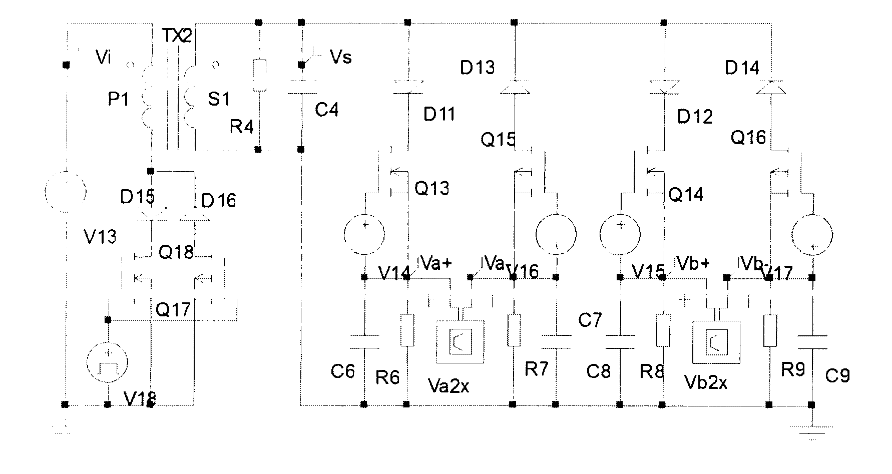
[0081]FIG. 16 is an AC inverter power source, the MOS tubes Q25, Q27 and the like form a type A unit circuit SBPA, the common drain electrodes are connected with the transformer TX2 to form a basic circuit (2.2), the transformer secondary side is a dynamic rectification circuit (3.4) composed of Q17, Q18, Q19, Q20, Q23, Q24, Q28, Q29, C2 is a capacitor with smooth action, V17 is a mains supply, V18, V19, V25, V26 are positive and negative symmetrical VDvrs type synchronous driving signals, and V22, V24 are VDvrh type high-frequency driving signals. Assuming that the amplitude of the input voltage V17 is 280V, the transformation ratio of the transformer TX1 is 1:0.3, the load resistor R7 is 50 Ohm, and the AC voltage V0 with 80V output amplitude is obtained on the resistor R7. In the simulation waveform of FIG. 72, the components are successively as follows: input voltage Vi, double-sideband square-wave voltage Vs enveloped as sine wave at transformer secondar...

embodiment 2

DC Inverter Power Source

[0082]FIG. 17 is a DC inverter power source, and MOS tubes Q33, Q34, Q37, Q38 form a main circuit. Because the input voltage is DC, the polarities of the MOS tubes forming the unit circuit are the same, and meanwhile, the diodes connected with the MOS tubes are omitted. The external voltage V16 is a 311V DC voltage, the driving signals V24, V25 are square-wave signals of 50 Hz, V25 delays 10 ms, the driving signals G1, G3 are high-frequency square-wave signals generated by Q29, Q30 and enveloped as sine-wave steamed bun wave, and G3 delays 10 ms. During the first 10 ms period, Q33, Q38 are conducted, the DC voltage flows across the TX3 primary side winding, Q33, R12, Q38 to form a loop, a sine-wave forward steamed bun wave high-frequency square-wave voltage identical to the G1 envelop is generated on R12, and a double-sideband sine-wave steamed bun wave high-frequency square-wave voltage is generated on the secondary side of TX3. During the last 10 ms period,...

embodiment 3

AC Voltage-Stabilized Power Source

[0088]FIG. 18 is the schematic circuit of the AC voltage-stabilized power source, power devices Q1, Q3 form a type A unit circuit SBPA, the resistor R7 is connected with the common source electrodes to form a unit circuit (2.1), the amplitude height modulation equivalent resistor AHM20k(Vo)1 and the resistor R6 are biasing circuits of grid electrodes of Q1, Q3, and the input voltage Vi is sine wave with 360V amplitude. The output voltage Vo tracks the grid electrode voltages of Q1, Q3. When the upper biasing resistor varies between 10 k and 100 k, the output voltage V0 varies between 300V and 170V, i.e. the AC output voltage is adjustable, and FIG. 74 is the simulation waveform of the output voltage. When the load resistor R7, the input voltage Vi or the temperature T varies, the output voltage Vo correspondingly varies, the amplitude height modulation circuit (4) is started at the moment, and the result of closed-loop control enables the output vol...


PUM


Abstract

The invention discloses a green power converter which omits the pulse width modulation (PWM) technique in the traditional power converter, does not have high-frequency power device, does not generate EMI interference, simultaneously adopts the symmetry basic primitive (SBP) technique, the amplitude high modulate (AHM) technique and the dynamic rectification (DR) technique, and only needs to perform traditional power conversion on a small part of the input power so as to acquire the whole output power, namely that a large part of the output power neither need traditional power conversion nor need to pass through a magnetic core transformer. The input AC voltage neither needs to be rectified and filtered nor has large inductance and large capacitance, thus the power factor is 1, and the total harmonic distortion (THD) is 0. A transformer secondary side adopts dynamic rectification, can acquire a DC circuit, and can also acquire an AC voltage. The circuit complexity, the power consumption and the failure rate of the whole green power converter are greatly lowered, and the power converter can be applied in all the fields to replace the traditional power converter.

Description

TECHNICAL FIELD[0001]The invention relates to a power converter.BACKGROUND TECHNOLOGY[0002]Traditional power conversion adopts the pulse width modulation (PWM) technique, the circuit is complex and difficult to adjust, all power devices work at high-frequency range, an intense EMI interference is generated, so that the sine wave voltage output by the power grid is seriously distorted, and the intense EMI interference is the greatest pollution source to the power grid. If there is no traditional power converter, and the power grid world is a blue sky. Besides the investment or disconnection of electric equipment, there is no other pollution source any more.[0003]The whole input power by traditional power conversion must be subject to power conversion before becoming an output power. The whole converted power must pass through a magnetic core transformer to reach the output end. The input power is subject to traditional power conversion, which means more investment and payment on cost...

Claims


Application Information

Patent Timeline
Patent Type & Authority Applications(United States)
IPC IPC(8): H02M7/537H02J1/00
CPCH02M1/4208H02M3/07Y02B70/1475Y02B70/126H02M3/33592Y02B70/10H02M1/088
Inventor YU, BAICHOU
Owner YU BAICHOU
Why Eureka
Try Eureka