Three-dimensional imaging device and viewpoint image restoration method

Inactive Publication Date: 2013-01-10
FUJIFILM CORP
View PDF0 Cites 14 Cited by
  • Summary
  • Abstract
  • Description
  • Claims
  • Application Information

AI Technical Summary

Benefits of technology

[0037]According to the present invention, since image quality at positions corresponding between individual viewpoint images is restored using a restoration filter according to a

Problems solved by technology

It is known that, when imaging an object body as a subject on an imaging plane of an image sensor via an optical system such as a zoom lens, the image capture

Method used


Image

  • Three-dimensional imaging device and viewpoint image restoration method
  • Three-dimensional imaging device and viewpoint image restoration method
  • Three-dimensional imaging device and viewpoint image restoration method

Examples


Example

[0058]Hereinafter, embodiments of a monocular three-dimensional imaging device according to the present invention will be described with reference to the accompanying drawings.

[0059](Overall Configuration of Imaging Device)

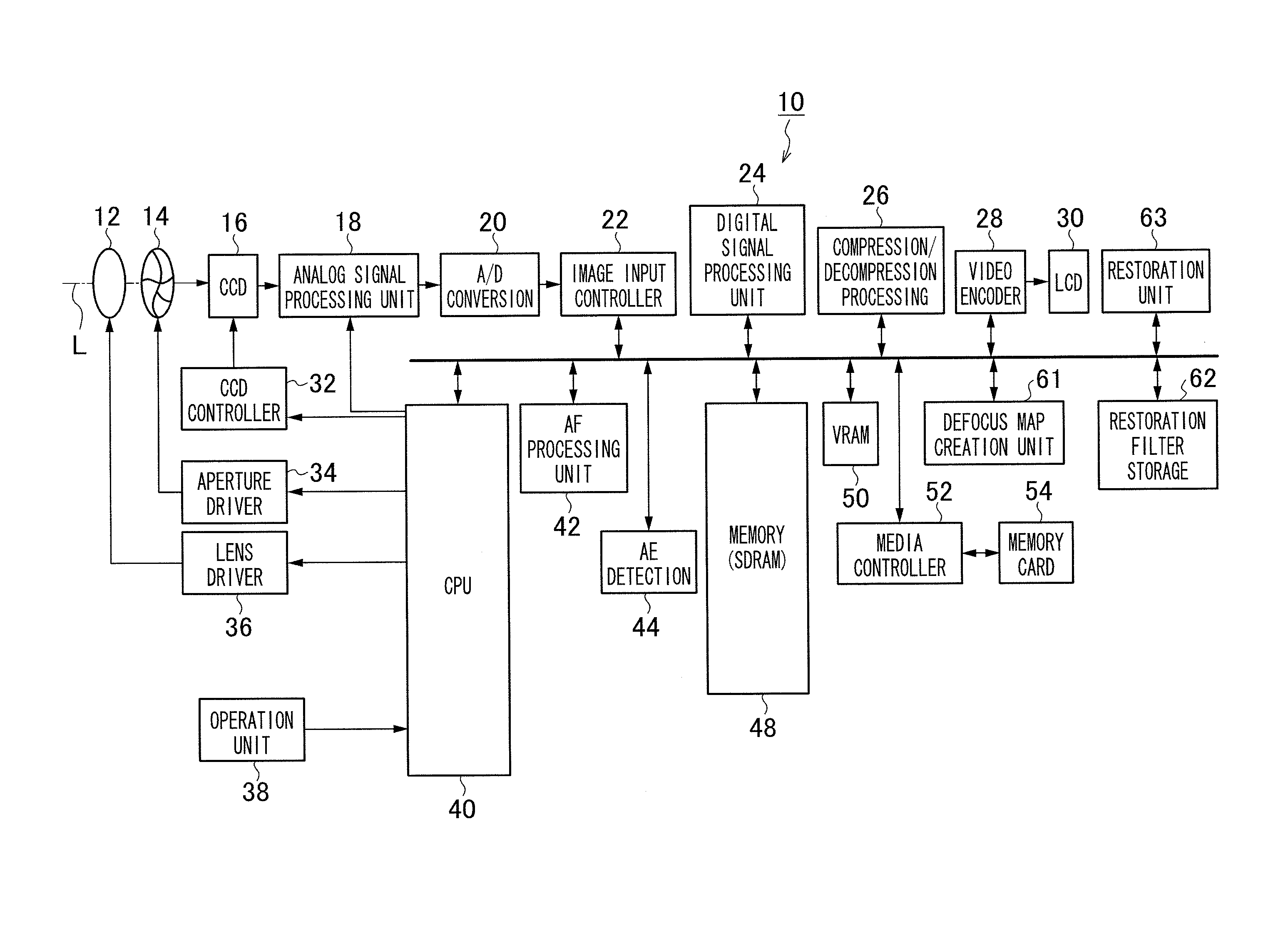
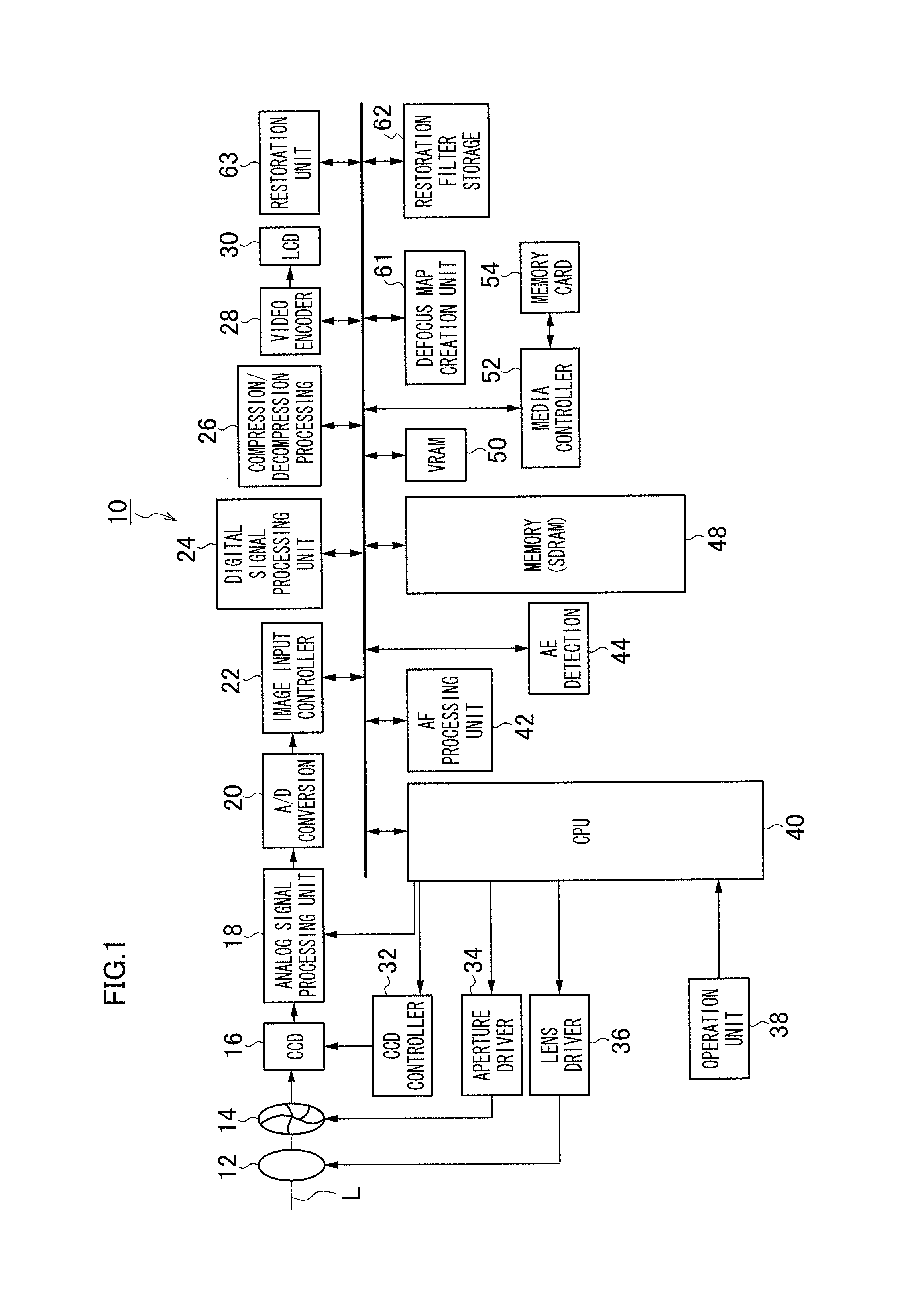
[0060]FIG. 1 is a block diagram illustrating an embodiment of a monocular three-dimensional imaging device 10 according to the present invention.

[0061]This monocular three-dimensional imaging device 10 records captured images in a memory card 54, and an overall operation of the device is integrally controlled by a central processing unit (CPU) 40.

[0062]The monocular three-dimensional imaging device 10 includes an operation unit 38 such as a shutter button, a mode dial, a playback button, a MENU / OK key, a cross key and a BACK key. Signals from the operation unit 38 are inputted to the CPU 40, and the CPU 40 controls individual circuits in the monocular three-dimensional imaging device 10 based on the inputted signals to perform, for example, lens driving control, a...


PUM


Abstract

A three-dimensional imaging device (10) according to an aspect of the present invention, which outputs first and second viewpoint images due to a pupil division on a light flux from a single imaging optical system (12, 14), includes a defocus map calculation unit (61) calculating a defocus map representing a defocus amount at each position in the first and second viewpoint images; a restoration filter storage (62) storing restoration filters corresponding to the defocus amount and an image height at each position in the viewpoint images, the restoration filters being deconvolution filters based on a point image intensity distribution representing an imaging performance of the imaging optical system; and a restoration unit (63) selecting a restoration filter, which corresponds to the defocus amount and the image height at each position in the viewpoint images, for each position in the first and second viewpoint images, and restoring the first and second viewpoint images by performing a deconvolution for each position in the first and second viewpoint images based on the selected restoration filter.

Description

TECHNICAL FIELD[0001]The present invention relates to a monocular imaging device, and specifically relates to a technology for imaging a subject image having passed through two regions of an image capturing lens different in direction on an image sensor, respectively and acquiring different viewpoint images.BACKGROUND ART[0002]Conventionally, from among this kind of monocular three-dimensional imaging device, one having an optical system illustrated in FIG. 9 is known (Patent Literature 1).[0003]In this optical system, subject images passing through regions of a main lens 1 and relay lens 2 different in right and left directions undergo pupil division using a mirror 4, and form images on image sensors 7 and 8 via imaging lenses 5 and 6.[0004]Portions (A) to (C) in FIG. 10 are diagrams illustrating separation of images imaged on the image sensors depending on differences at front focus, at focus (best focus) and at rear focus, respectively. In FIG. 10, for the purpose of comparison o...

Claims


Application Information

Patent Timeline
IPC IPC(8): G06T5/00H04N13/02H04N13/232
CPCG03B35/08G06T5/003H04N13/0257H04N13/0217H04N13/0232G06T2207/10028H04N13/232H04N13/257H04N13/218
Inventor IWASAKI, YOICHI
Owner FUJIFILM CORP
Why Eureka
Try Eureka