Pressure enhancing device

Inactive Publication Date: 2013-01-17
WRIGHTSOLAR
View PDF6 Cites 7 Cited by
  • Summary
  • Abstract
  • Description
  • Claims
  • Application Information

AI Technical Summary

Benefits of technology

The present invention provides a device for use in domestic, commercial, and industrial plumbing arrangements. The device can be used in a solar fluid heating system or a fluid and heat saving arrangement. The device is a low-cost, low-noise, and economical pump that can be manually or automatically activated based on flow rate, pressure, or temperature. The device allows for efficient transfer of fluids and can be used in a variety of plumbing arrangements. The technical effects of the invention include improved water saving, reduced heat loss, and improved pumping efficiency.

Problems solved by technology

A common problem is that in order to pump a fluid from a first point to a second point especially where there is insufficient pressure differential for the fluid to travel by gravity (hydraulic head at one end being greater than that at the other), a pump is typically fitted in-line to the flow of fluid (e.g. a fluid conduit or pipe)—this pump is commonly referred to as a shunt pump if it is close to the source or an on-line booster if it is more remote from the source, both of which are installed on-line (i.e. within the line of the primary flow conduit).
There are several disadvantages with this arrangement, the details of which depend upon the particular application or purpose of fluid transport or pumping.
For example, if seeking to enhance a pressure of fluid at one of a plurality of ‘downstream’ outlets, a pump is typically sized to achieve the maximum flow rate required for any outlet and the maximum pressure required at any outlet, such that the pump is not running most efficiently and considerably more power is used than is necessary.
A further disadvantage with many pumps is that if the pump breaks down, the passage of fluid may be prevented even at the un-pressurised pressure.
This is typical because there is significant pressure loss pumping over long distances.
Pump efficiencies are sacrificed as a single speed pump pumping at its duty point is not possible and less efficient pumping arrangements such as multiple speed pumps or duty assist pumps are used.
However, at times when demand is low and a single pump at the source or just gravity flow would have sufficed the on-line pump now switched off within the primary flow conduit creates considerable head loss and maintenance issues.
In a domestic plumbing application, the problem of variations in flow is further complicated by the requirement for a certain minimum pressure to operate at individual outlets (e.g. showers).
With any on-line pump, if it is turned off or breaks down there are considerable head losses as water forces through the pump and flows that could be achieved without the pump can no longer be achieved.
With a traditional shower pump, such as the Watermill Wasp™ 50, there is a danger of it either taking too much water to a shower so that it starves the system (and perhaps a washing machine feed stops working) or if installed into a primary conduit feeding other taps and appliances, when turned off or broken down it again causes a blockage (and perhaps a washing machine feed stops working).
To avoid this outcome, a separate pipe to the shower from a hot water system may be fitted, which extra materials and labour (and the requirement of a separate electricity supply) render this an expensive option.

Method used


Image

  • Pressure enhancing device
  • Pressure enhancing device
  • Pressure enhancing device

Examples


example 1

[0083]A supply feed (first conduit) of 22 mm diameter to a shower has an external head of pressure whereby without a pump fluid is supplied to the shower at 3.3 litres per minute, which would be considered a poor shower. The supply feed was then fitted with a device according to the present invention in which the second conduit has a diameter of 15 mm and is fitted with a pump of varying power. The effect of increasing pump power in this situation is examined. The results are shown in Table 1.

TABLE 1Pump power / WShower flow-rate / Lmin−1Notes03.315 (12 V)6.3Pump warm30 (19 V)7.7Pump hot but not too hot60 (24 V)8.2Pump hot and too hot

[0084]As can be seen from the above, the efficiency of the pump for a particular system drops off dramatically when the power of the pump is increased.

example 2

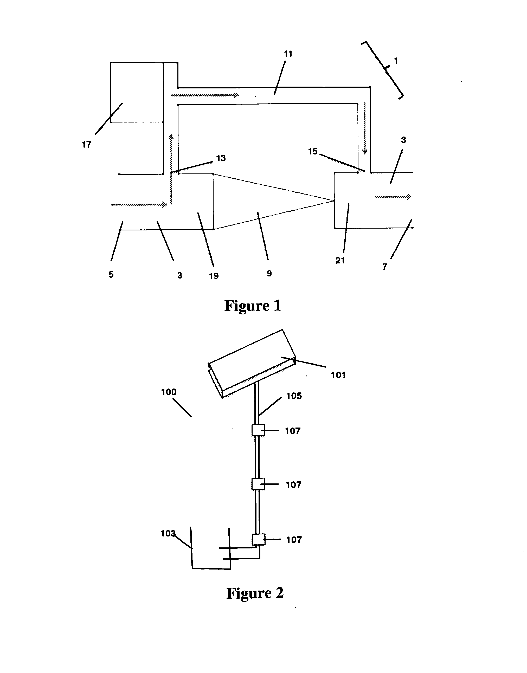
[0085]The following sets out the flow and pressure requirements for the application of a device of the present invention in pumping water from a tank at ground level through copper pipe to a solar panel at 15 metres height, using a relay arrangement of three devices in series. The data is summarized in the following table:

TABLE 2Scenario IScenario IIScenario IIIPipe diameter8 mm10 mm15 mmVolume per0.050.781.77metre length / lTotal volume / l0.751.182.66Flow rate2.5 l / min2.5 l / min2.5 l / minTransit time18 s28 s64 sPipe length15 m15 m15 mHydraulic head15 m15 m15 mHead loss / m0.2630.0840.03Pressure19 m head16.3 m head15.45 m headrequired

[0086]In order to achieve the flow rates and pressure required in a smaller diameter pipe, three devices of the present invention may be utilized in relay, sized to pump fluid in three 5 meter sections at the required flow-rate to overcome the head loss significantly more power and cost effectively than a single high pressure pump at ground level.


PUM


Abstract

A device is provided for increasing fluid pressure, the device having a first conduit having a fluid inlet and outlet, the first conduit provided with a non-return valve and a second, bypass, conduit having bypass inlet and by pass outlet connected to the first conduit either side of the non-return valve, which bypass is provided with a pumping means. The pump may be sized such that the device can deliver a high pressure of fluid to a low flow-rate demand outlet downstream thereof whilst the device allow a high flow-rate demand downstream of the device to be supplied at low pressure as and when required resulting in a much cheaper, more efficient and more durable pumping arrangement, useable in several applications.

Description

FIELD OF THE INVENTION[0001]This invention is concerned with a device and method for enhancing the pressure of a fluid and / or enhancing the transport of a fluid. It finds particular application in domestic plumbing (such as supply of water to a home or enhancement of pressure to an individual outlet such as a shower), civil / municipal water engineering, transport of oil and gas and medical applications.BACKGROUND OF THE INVENTION[0002]Pumping and transport of fluids is commonplace in many industries and is an essential step in various processes and applications in a range of industries. Particular industries of interest in the pumping or transport of fluid include chemical processing, oil and gas exploration and extraction, municipal water and sewage systems, domestic plumbing, microfluidic applications and medical applications.[0003]A common problem is that in order to pump a fluid from a first point to a second point especially where there is insufficient pressure differential for ...

Claims


Application Information

Patent Timeline
IPC IPC(8): F17D3/00A61M60/126A61M60/152A61M60/232A61M60/515A61M60/554A61M60/562
CPCA61M1/10B41J2/17596F04B19/006A61M1/125F24D3/06F24D17/0078A61M1/122F04F5/10Y10T137/87265A61M60/148A61M60/554A61M60/232A61M60/562A61M60/515A61M60/152A61M60/126B41J2/175E03B5/00E03B7/07
Inventor WRIGHT, ALAN DEREK
Owner WRIGHTSOLAR
Why Eureka
Try Eureka