Method for manufacturing melt-spinning alloys and apparatus thereof

a technology of alloys and manufacturing methods, applied in the field of metal materials, can solve the problems of reduced yield, production interruption, non-uniform thickness of melt-spinning alloy strips, etc., and achieve the effects of low cost, reduced efficiency, and reduced volatilization and burning of volatile metals or alloys

Inactive Publication Date: 2013-01-17
GRIREM ADVANCED MATERIALS CO LTD
View PDF1 Cites 16 Cited by
  • Summary
  • Abstract
  • Description
  • Claims
  • Application Information

AI Technical Summary

Benefits of technology

[0032]The melting environment of a common rapid-quenching furnace is generally in negative pressure, which will cause some volatile metals or alloys having a relatively large vapor pressure at high temperature to volatilize greatly and burn, to cause inaccurate composition of the melt-spinning alloys. While in this method, the pressure of the melting environment may be controlled at 5 MPa at most, the volatilization and burning of volatile metal or alloy are reduced greatly during the melting.
[0033]Fourth, continuous production is achievable, the efficiency is high, and the cost is low.
[0034]For the method for manufacturing melt-spinning alloys in the application, a tundish is utilized to jet the molten alloy, an automatic feeding device is provided, continuous production can be achieved; furthermore, the nozzle on the bottom of the tundish may be provided with a plurality of openings, this may increase the jet flow of the molten alloy exponentially, thereby improving the production efficiency and reducing the production cost. This method is quite suitable for industrial production. For example, at present, the jet flow of the molten alloy in the common rapid-quenching methods is about 1.0-1.5 kg / min, while the jet flow of the molten alloy in the application can reach 20 kg / min at most.
[0035]By the method for manufacturing melt-spinning alloys in the application, problems of rare earth permanent magnetic materials during the preparation process can be solved effectively; materials prepared by this method are mainly neodymium iron boron series and rare earth iron nitrogen series of magnetic materials; compared with the existing methods, the prepared materials have higher performance.

Problems solved by technology

The above methods generally have the following defects: first, it is unable to precisely control the jet speed of the molten alloy to the cooling roller, resulting in non-uniform thickness of the melt-spinning alloys strip and reduced yield; second, the molten alloy nozzle may be blocked easily, resulting in production interruption; third, a higher cooling speed cannot be obtained.
Besides, the rapid-quenching methods disclosed in the above patents generally have one fetal weakness: the molten alloy is basically jetted to the cooling roller from a small single hole, which causes extremely low production efficiency and too high cost.

Method used


Image

  • Method for manufacturing melt-spinning alloys and apparatus thereof
  • Method for manufacturing melt-spinning alloys and apparatus thereof
  • Method for manufacturing melt-spinning alloys and apparatus thereof

Examples


embodiments 1-30

of the Application

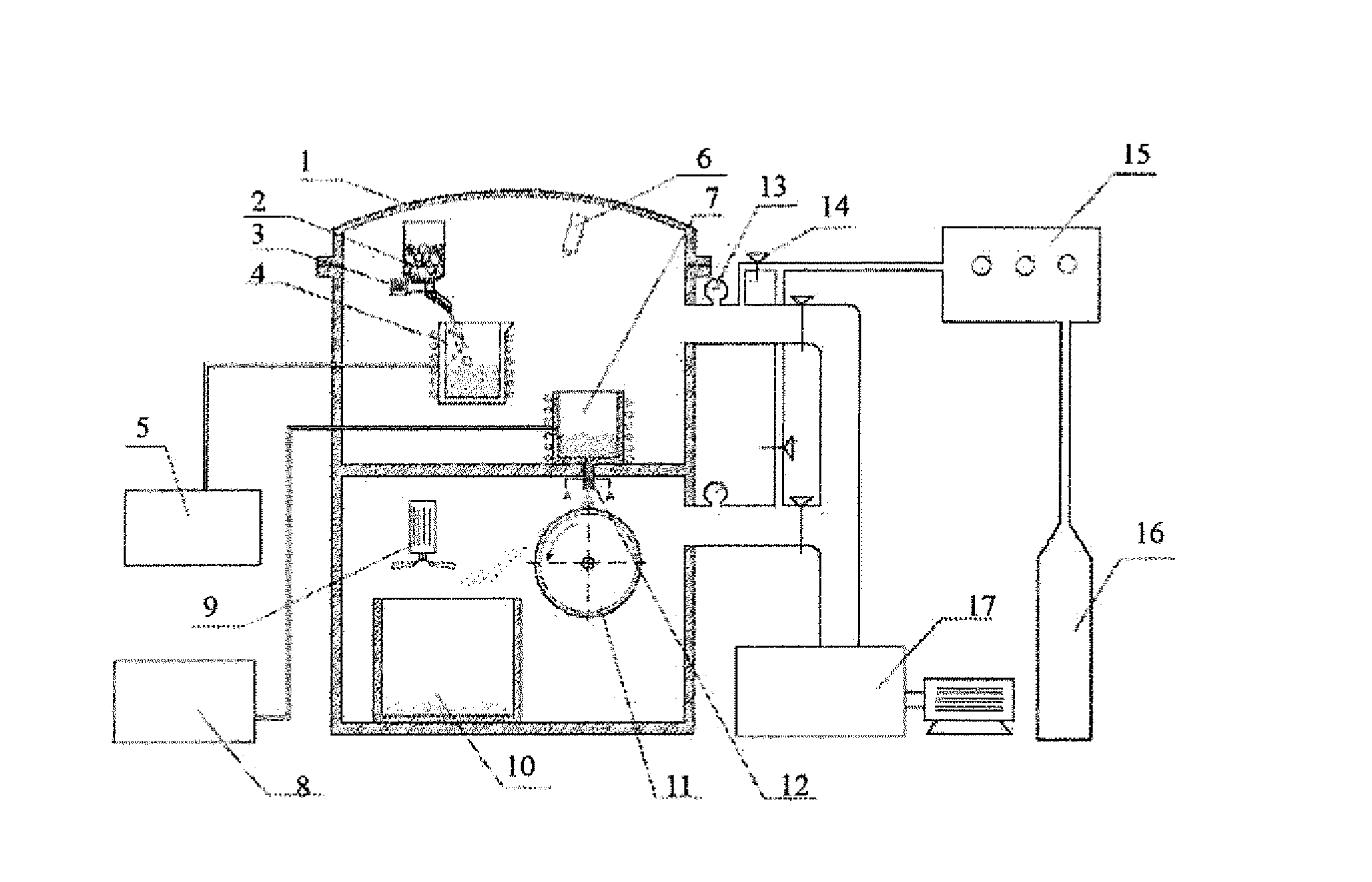
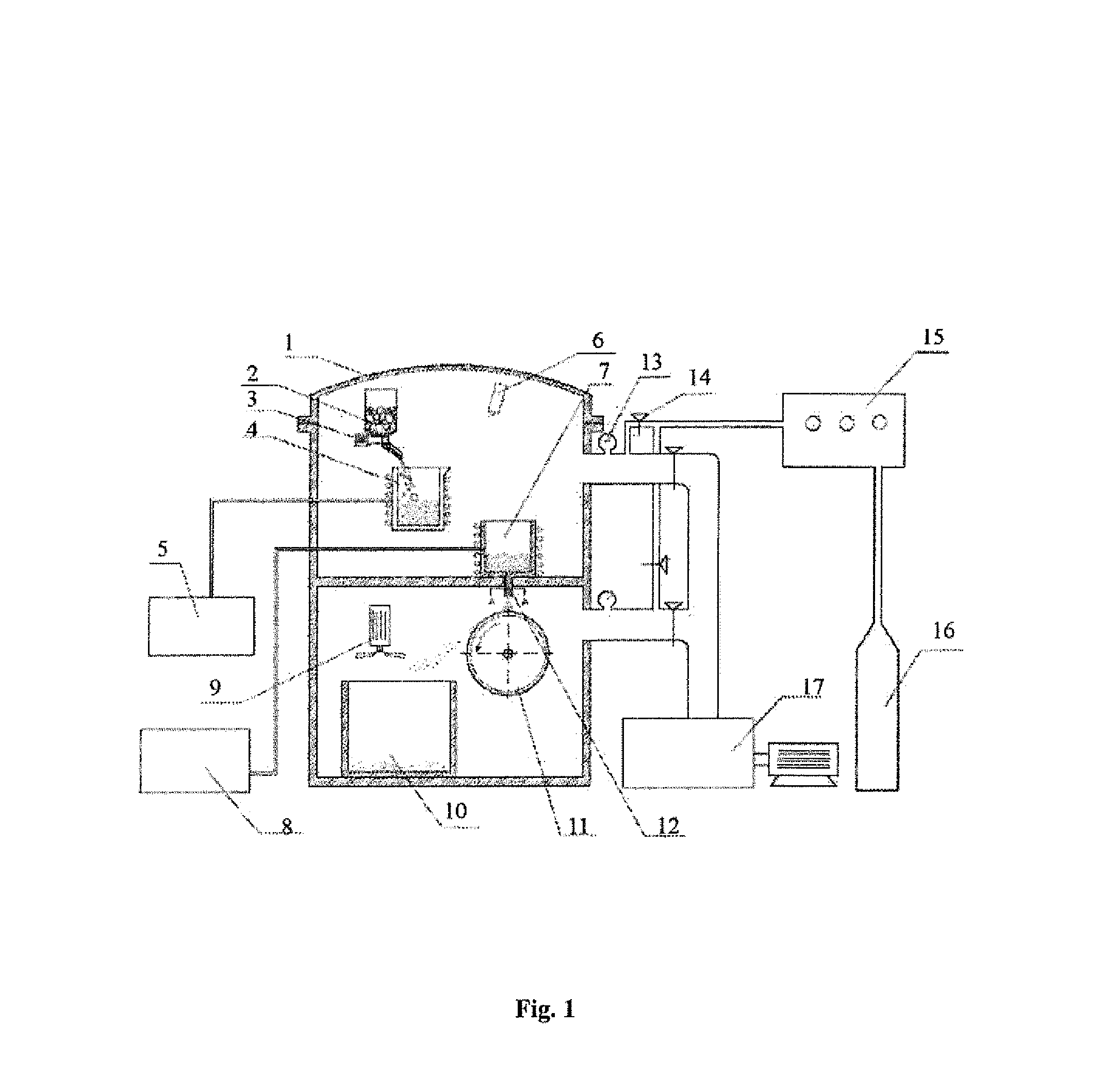
[0061]Apparatus: the apparatus for manufacturing melt-spinning alloys in the application, with a structure as shown in FIG. 1.

[0062]Implementation Process:

[0063](1) Preparation of Neodymium Iron Boron Series of Magnetic Materials

[0064]This series of materials may be Rx(Fe1-yMy)100-x-zBz, this material mainly contains R2Fe14B, 4≦x≦15 at %, 0.5≦z≦20 at %, 0≦y≦0.5 at %, and M is one or more of Zr, Hf, Mn, Ti, Si, V, Co, Ni, Cr, Mo, Al, Nb, Ga, Ta, Cu, Zn.

[0065]Raw materials with this composition were put into the storage bins of the melting crucible and feeding system, the circulating water system was opened, and the melting and rapid-quenching two chambers were evacuated to below 1.0*10−3 Pa. The vacuum system was closed, and the two chambers were inflated with argon to 5.0*104 Pa.

[0066]The crucible heating system and the tundish heating system were opened to start melting raw materials; simultaneously, the tundish and the nozzle on the bottom of the tundish were pre...

embodiments 31-55

of the Application

[0074]Apparatus: the same as that used in embodiments 1-30.

[0075]Preparation Process:

[0076]Raw materials with certain composition were put into the storage bins in the melting crucible and feeding system, the circulating water system was opened, and the melting and rapid-quenching two chambers were evacuated to below 1.0*10−3 Pa. The vacuum system was closed, and the two chambers were inflated with argon to 5.0*104 Pa.

[0077]The crucible heating system and the tundish heating system were opened to start melting raw materials; simultaneously, the tundish and the nozzle on the bottom of the tundish were pre-heated. After raw materials inside the crucible were completely molten, the cooling roller and the cooling fan in the receiving bin were opened, the surface line velocity of the cooling roller was adjusted, the molten alloy inside the crucible was poured into the tundish, the alloy solution was jet from the nozzle, and rapid-quenching was started.

[0078]During the r...


PUM

PropertyMeasurementUnit
velocityaaaaaaaaaa
surface line velocityaaaaaaaaaa
cross-sectional areaaaaaaaaaaa

Abstract

The application provides a method for manufacturing melt-spinning alloys and an apparatus thereof, which belongs to the technical field of metal materials and preparation thereof. The main feature of method including steps of melting alloy and jetting the molten alloy for rapid-quenching is that alloy melting and rapid-quenching are respectively implemented in independent environments, and the pressure of the two environments can be adjusted separately. The method can realize uniformity control of rapid-quenching velocity by controlling the melting and quenching pressure respectively, which has the advantages of increased rapid-quenching cooling rate, improved melt-spinning alloys thickness uniformity, reduced probability of nozzle clogging.

Description

TECHNICAL FIELD OF THE INVENTION[0001]The application relates to the technical field of metal materials and preparation thereof, in particular to a method for manufacturing melt-spinning alloys and an apparatus thereof.BACKGROUND OF THE INVENTION[0002]Rapid-quenching technology has been widely applied in manufacturing various microcrystalline or amorphous metals and alloys, and has been more widely applied in the field of special magnetic alloy especially. For example, the rapid-quenching method is utilized to manufacture Fe—Ni series, Fe—Ni—Co series, Re2Fe14B series and rare earth iron nitrogen series alloys. The rapid-quenching method requires devices to be able to provide an extremely great cooling capacity (104-106K / s), so that high-temperature melts would obtain a large degree of supercooling within an extremely short time. At present, the industrial melt rapid-quenching method generally refers to that the molten alloy is jetted to a cooling roller that rotates rapidly at a ce...

Claims


Application Information

Patent Timeline
Patent Type & Authority Applications(United States)
IPC IPC(8): C21D1/00F27D99/00C21D11/00
CPCB22F9/08B22F2009/048B22F2009/0888H01F1/0571B22D11/0602B22D11/10H01F1/059B22F2999/00B22D11/144B22F2203/13
Inventor LI, HONGWEIYU, DUNBOLUO, YANGLI, KUOSHELI, SHIPENGWANG, MINYUAN, YONGQIANG
Owner GRIREM ADVANCED MATERIALS CO LTD
Why Eureka
Try Eureka