Input device with elastic membrane
a technology of input device and elastic membrane, which is applied in the direction of mechanical control device, manual control with multiple controlled members, manual control with single controlling member, etc., can solve the problems of complexity, cost and size, and achieve the effect of avoiding buckling, enhancing the force of the polymer membrane, and hampering unwanted rotational movements
- Summary
- Abstract
- Description
- Claims
- Application Information
AI Technical Summary
Benefits of technology
Problems solved by technology
Method used
Image
Examples
first embodiment
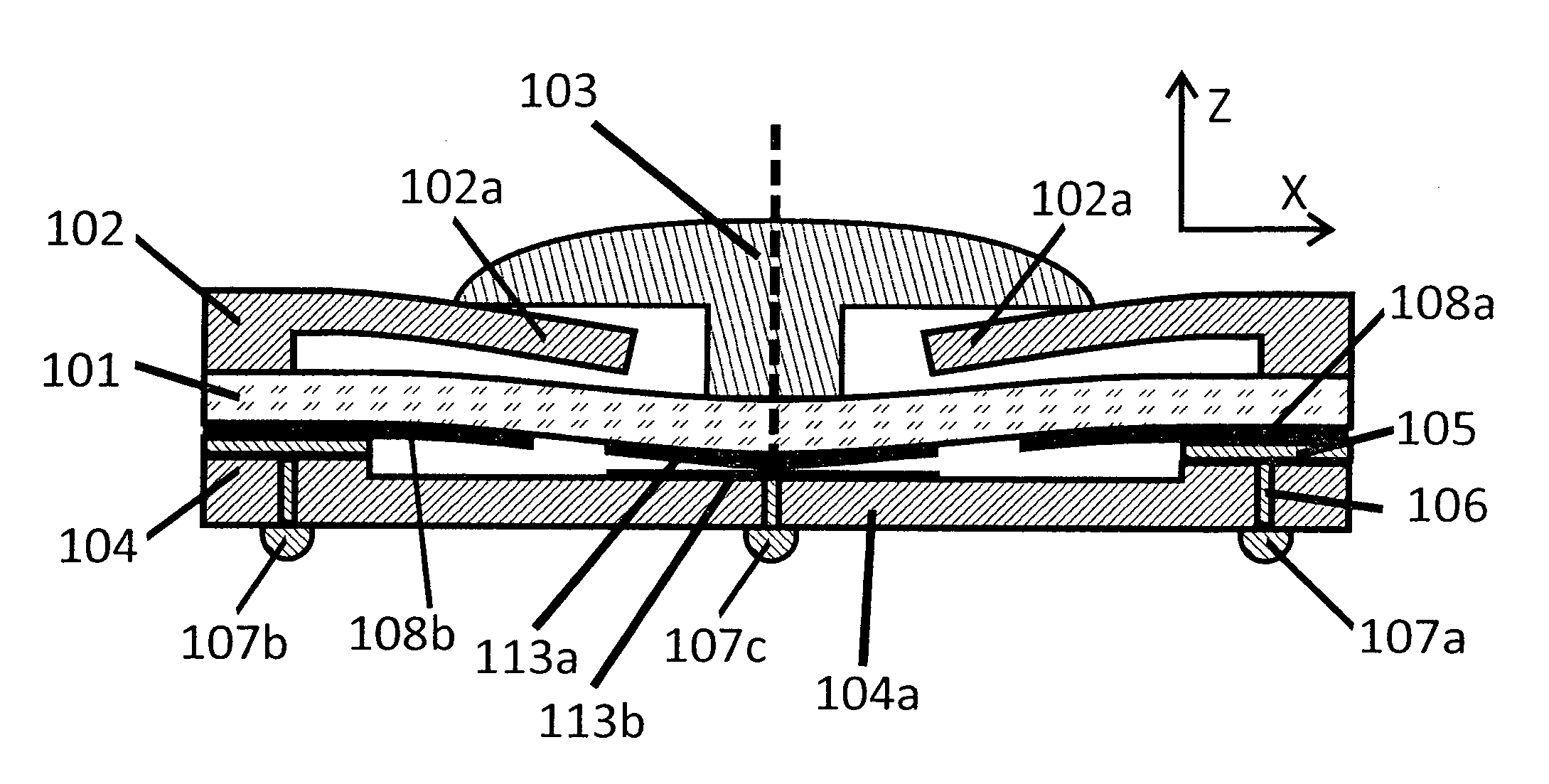
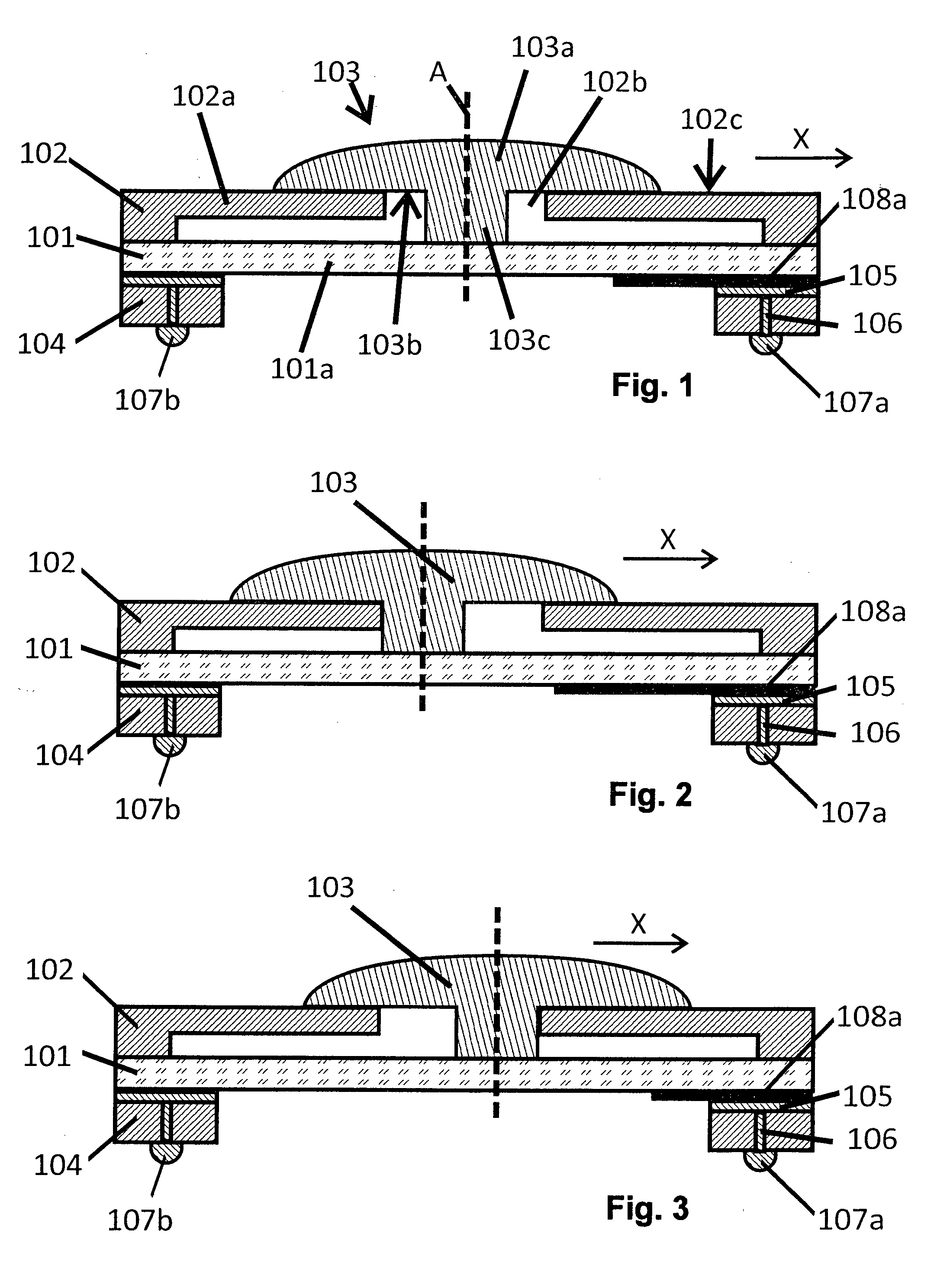
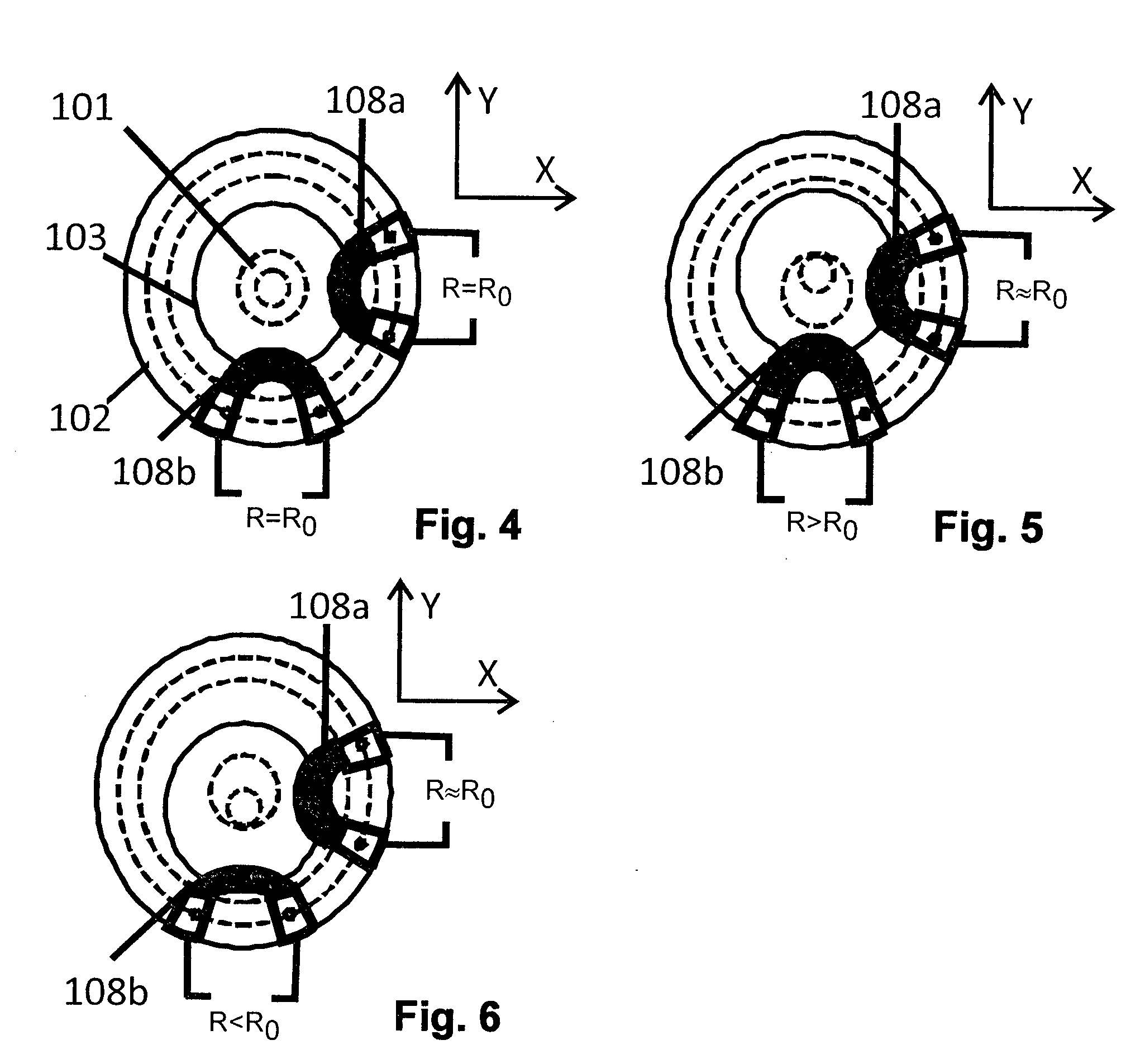
[0091]One possible embodiment of the present invention is a self-centering joystick as shown in FIGS. 1-6. This embodiment comprises a polymer membrane 101 held in a rigid frame 102. In the embodiment shown, membrane 101 and frame 102 are rotationally symmetric about an axis A extending perpendicularly to membrane 101. A handle 103 is mounted in frame 102 and connected to membrane 101.
[0092]Frame 102 forms an upper lid 102a extending parallel to membrane 101 and having a central opening 102b. The top side (i.e. the side facing away from membrane 101) of lid 102a forms a flat support surface 102c.
[0093]Handle 103 can e.g. directly form a button operated by a user, or it may be connected to a rod or stick for easier manipulation. It has a head section 103a with a flat bottom or sliding surface 103b resting against support surface 102c. A shaft section 103c of handle 103 extends from head section 103b through opening 102b and is anchored in membrane 101, e.g. by welding or gluing.
[009...
second embodiment
[0102]The second embodiment of the device shown in FIGS. 7 and 8 substantially corresponds to the first embodiment, with the exception that it is designed to use a capacitive measurement for determining the position of handle 103.
[0103]For this purpose, membrane 101 is equipped with at least one top electrode 111 and at least one bottom electrode 108a-108d, both of which are acting as sensing electrodes. The top and bottom electrodes are arranged on opposite sides of the membrane, and their mutual electrical capacitance depends on their size and distance. As mentioned above, both size and distance change when membrane 101 is stretched or compressed due to a movement of handle 103, i.e. the capacitance is a measure of the position of handle 103.
[0104]As can be seen in FIG. 8, which illustrates the positions of the bottom electrodes 108a-108d, there are four such electrodes arranged at the periphery of the four quadrants of membrane 101. At least two bottom electrodes (or, more genera...
third embodiment
[0108]The third embodiment, shown in FIG. 9, substantially corresponds to the first embodiment of FIGS. 1-6, but it comprises a limiter, in the following called the “second limiter”, preventing a displacement of handle 103 into a third direction Z perpendicular to membrane 101.
[0109]In the embodiment of FIG. 9, the second limiter comprises[0110]A slot 112a formed on handle 103 between the bottom side of head section 103a and a rigid plate 112b. Rigid plate 112b is mounted to shaft section 103c and extends parallel to membrane 101,[0111]A projection 112c formed on frame 102, extending parallel to membrane 101 and reaching into recess 112a. Projection 112c is formed by lid 102a of frame 102.
[0112]Slot 112a and projection 112c interlock in direction Z, thereby preventing a movement of handle 103 along direction Z, while allowing for a movement of handle 103 in directions X and / or Y.
PUM
| Property | Measurement | Unit |
|---|---|---|
| Fraction | aaaaa | aaaaa |
| Time | aaaaa | aaaaa |
| Angle | aaaaa | aaaaa |
Abstract
Description
Claims
Application Information
 - R&D
- Intellectual Property
- Life Sciences
- Materials
- Tech Scout
- Unparalleled Data Quality
- Higher Quality Content
- 60% Fewer Hallucinations
Browse by: Latest US Patents, China's latest patents, Technical Efficacy Thesaurus, Application Domain, Technology Topic, Popular Technical Reports.
© 2025 PatSnap. All rights reserved.Legal|Privacy policy|Modern Slavery Act Transparency Statement|Sitemap|About US| Contact US: help@patsnap.com


