
LED backlight drive circuit

a technology drive circuit, which is applied in the direction of electroluminescent light sources, lighting apparatuses, light sources, etc., can solve the problems of increasing power loss, compromising and increasing temperature, so as to improve the stability of led backlight drive circuit and reduce power loss and temperature

Inactive Publication Date: 2013-01-31
SHENZHEN CHINA STAR OPTOELECTRONICS TECH CO LTD
View PDF4 Cites 8 Cited by
  • Summary
  • Abstract
  • Description
  • Claims
  • Application Information

AI Technical Summary

Benefits of technology

The present invention provides an LED backlight drive circuit that solves the problems of large power loss and high temperature rise of the circuit. It achieves this by adding a constant-voltage unit between the LED lamp strings and the constant-current control circuit. This results in identical voltages across the constant-current control circuit, which decreases power loss and temperature. Thus, the LED backlight drive circuit improves stability.

Problems solved by technology

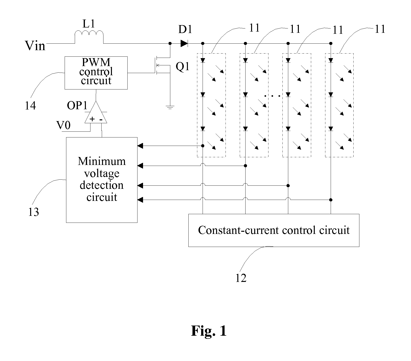
The voltage differences among these voltages will be applied to the constant-current control circuit 12 (balance IC) to cause an increase in power loss and, consequently, a rise in temperature of the balance IC, which will compromise stability of the LED backlight drive circuit.

Method used


Image

  • LED backlight drive circuit
  • LED backlight drive circuit
  • LED backlight drive circuit

Examples


Embodiment Construction

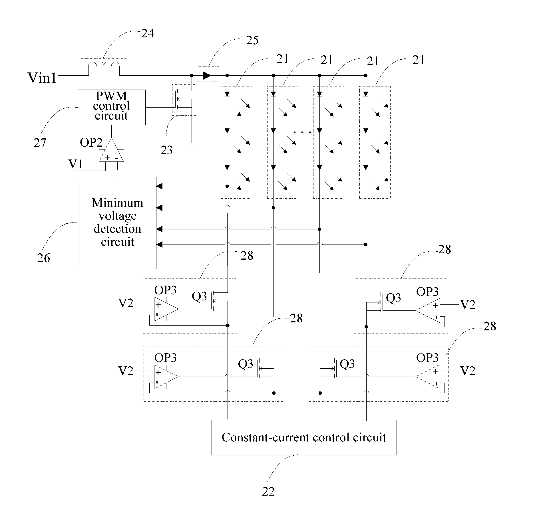
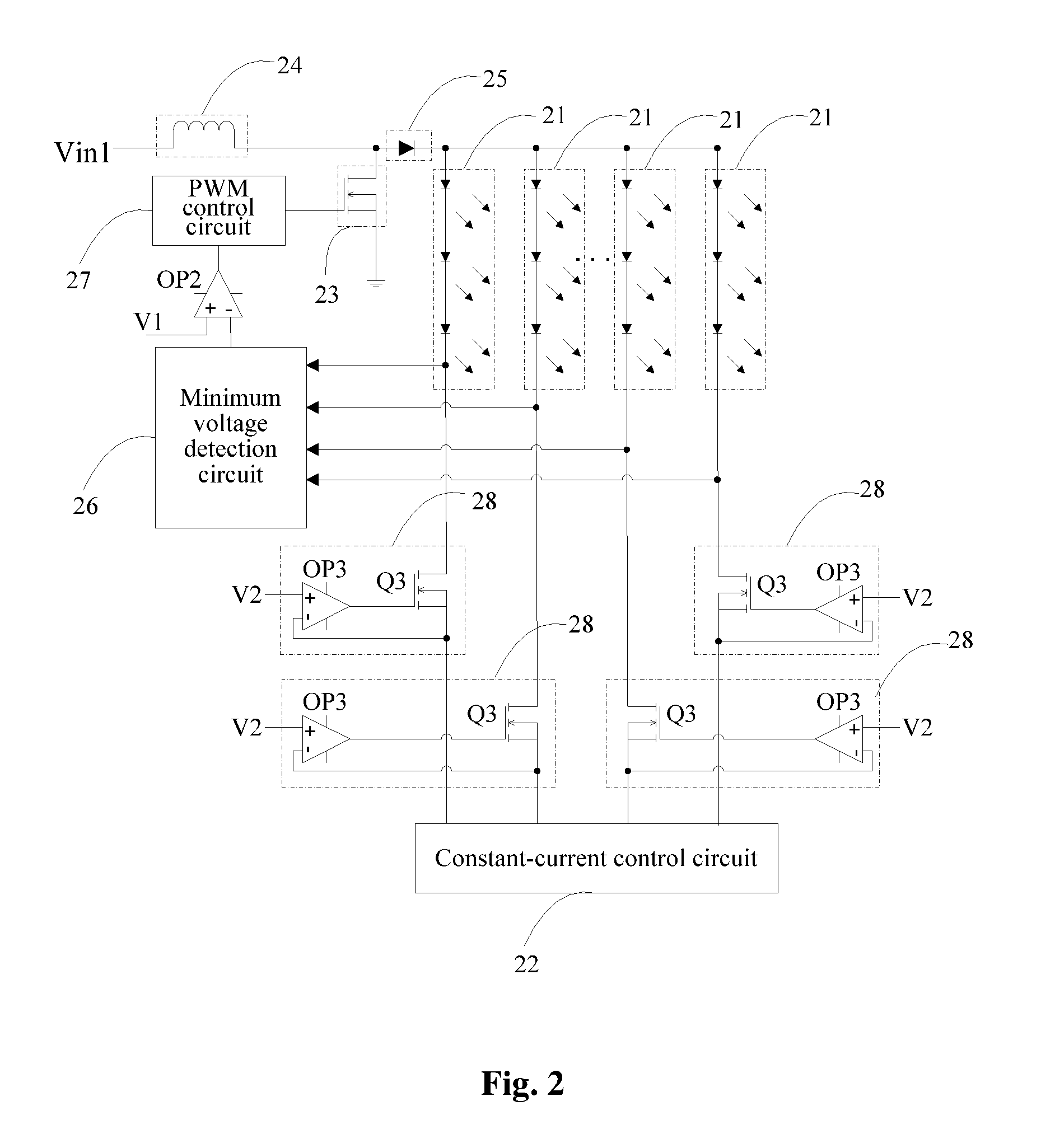
[0031]FIG. 2 illustrates a schematic circuit diagram of a preferred embodiment of an LED backlight drive circuit according to the present disclosure. As shown in FIG. 2, the LED backlight drive circuit comprises a voltage input terminal Vin 1, a plurality of LED lamp strings 21 connected in parallel, a constant-current control circuit 22, a switch unit 23, an inductor 24, a rectification anti-backflow unit 25, a minimum voltage detection circuit 26, a PWM control circuit 27, an operational amplifier OP2 and a plurality of constant-voltage units 28. The number of the constant-voltage units 28 is equal to the number of the LED lamp strings 21. The plurality of constant-voltage units 28 are connected between the plurality of LED lamp strings 21 and the constant-current control circuit 22 respectively. The constant-current control circuit 22 may be a balance chip (Balance IC) in this embodiment.

[0032]By additionally providing the constant-voltage unit 28 (a closed-cycle control system) ...


PUM


Abstract

An LED backlight drive circuit comprises a plurality of LED lamp strings connected in parallel, a constant-current control circuit for controlling magnitudes of currents flowing through the LED lamp strings to be the same, and a plurality of constant-voltage units. The number of the constant-voltage units is the same as that of the LED lamp strings. The constant-voltage units are connected between the LED lamp strings and the constant-current control circuit respectively. Each constant-voltage units comprises an MOS transistor and a first operational amplifier. The MOS transistor has a drain connected to a cathode of a corresponding LED lamp strings, a gate connected to an output terminal of the first operational amplifier and a source connected to the constant-current control circuit. The first operational amplifier has a positive input terminal connected to a reference voltage and an inverting input terminal connected to the source of the MOS transistor.

Description

BACKGROUND[0001]1. Technical Field[0002]The present disclosure relates to the field of light emitting diode (LED) backlight driving, and more particularly, to an LED backlight drive circuit.[0003]2. Description of Related Art[0004]Owing to development of related technologies and driven by users' demands, liquid crystal panels are made to have increasingly larger sizes. In light emitting diode (LED) backlight drive circuits of prior art large-size liquid crystal panels, a constant-current control circuit 12 (e.g., a balance IC) must be used to control a plurality of LED strings simultaneously to accomplish accurate control of the LED current of each of the LED strings.[0005]FIG. 1 is a schematic circuit diagram of an LED backlight drive circuit in a prior art large-size liquid crystal panel. As shown in FIG. 1, the LED backlight drive circuit comprises a voltage input terminal Vin, an inductor L1, a metal oxide semiconductor (MOS) transistor (MOSFET) Q1, a diode D1, a plurality of LE...

Claims


Application Information

Patent Timeline
Patent Type & Authority Applications(United States)
IPC IPC(8): H05B37/02
CPCH05B33/0827H05B45/46
Inventor GAO, XINMING
Owner SHENZHEN CHINA STAR OPTOELECTRONICS TECH CO LTD
Learn More