Multifunctional de-icing/Anti-icing system of a wind turbine

a wind turbine and multi-functional technology, applied in the direction of rotors, marine propulsion, vessel construction, etc., can solve the problems of low energy loss and low power consumption of melting ice, and achieve the effect of reducing the weight of articles and saving weigh

Inactive Publication Date: 2013-01-31
SAAB AB
View PDF6 Cites 33 Cited by
  • Summary
  • Abstract
  • Description
  • Claims
  • Application Information

AI Technical Summary

Benefits of technology

[0039]Thereby is also achieved that the de-icing / anti-icing system's conductive structures promotes for a thin shell which is beneficial, i.e. for saving weight.
[0040]An article made of a polymeric composite matrix can thereby integrate the conductive structures. The article's shell comprising the resin layer including the conductive nano structures will therefore be reinforced, since the conductive nano structures per se also promote for a strengthening of the shell, which also may reduce the article's weight.

Problems solved by technology

The nano structure (comprising e.g. carbon nano tubes CNT, carbon nano fibres, graphite nano wires etc.) has a very good thermal and electrical conductivity and since the nano structure can be situated near and beneath the outer surface of the component, the energy losses for melting the ice will be low which means low power consumption.

Method used


Image

  • Multifunctional de-icing/Anti-icing system of a wind turbine
  • Multifunctional de-icing/Anti-icing system of a wind turbine
  • Multifunctional de-icing/Anti-icing system of a wind turbine

Examples


first embodiment

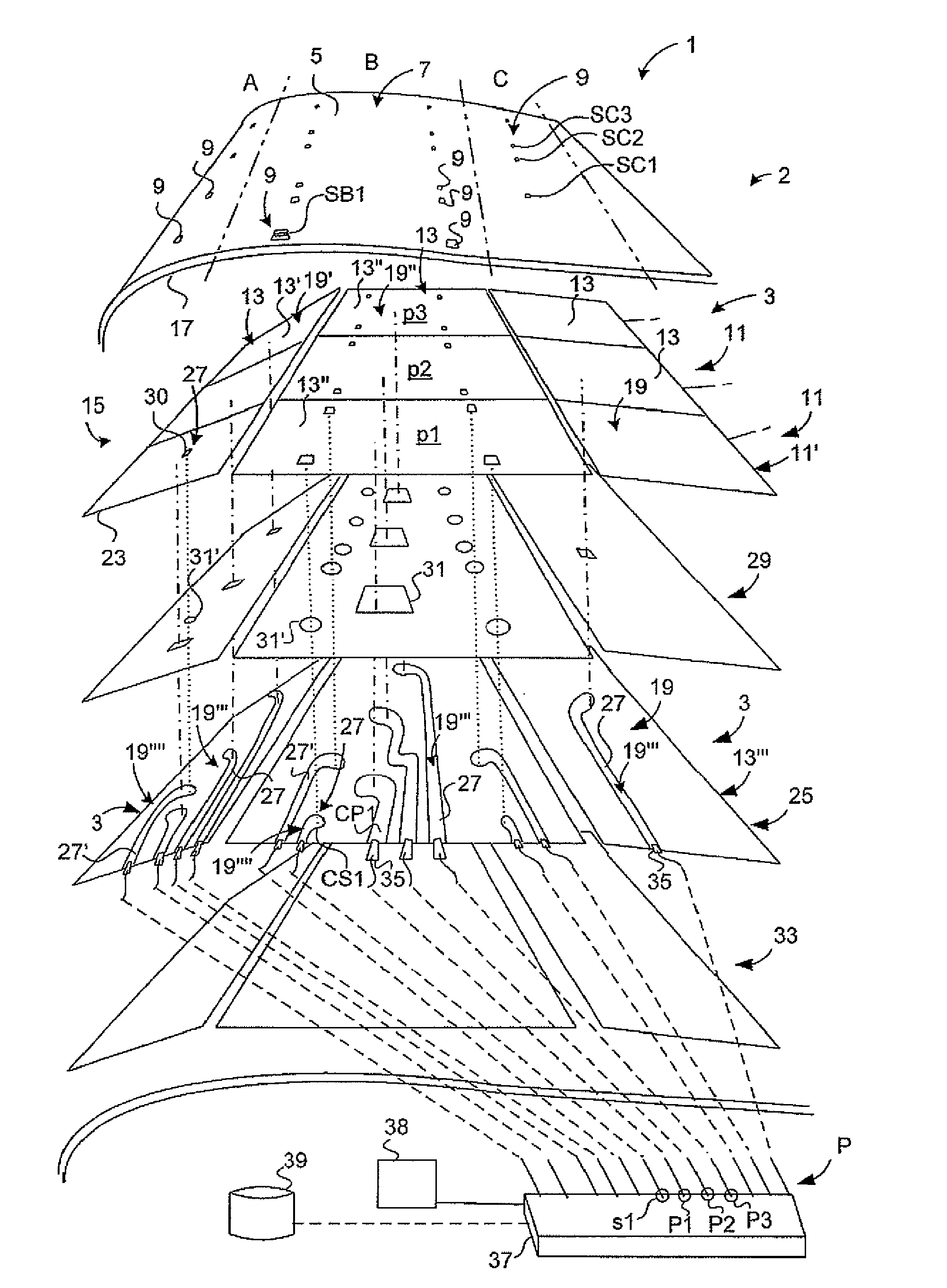
[0081]FIG. 1 schematically illustrates a de-icing / anti-icing system (system 1) according to a The illustration shows parts of the embodiment essential for understanding only. The system 1 comprises a wind turbine blade 2 including a plurality of conductive structures 3 embedded in a wind turbine blade shell. The shell includes an outer surface 5 being designed as an aerodynamic surface. The outer surface 5 thus serves as the aerodynamic surface, when the shell moves relatively the air or through the air. The outer surface 5 is a hard smooth surface of a lightning protection layer 7. The smoothness and hardness of the outer surface 5 are achieved by incorporating nano structure filaments at least into the outer surface, which nano structure also is conductive and acts for shielding the wind turbine blade's interior from an eventual lightning strike. The outer surface 5 further comprises sensors 9 for detection of ice. Several sets 11 of conductive structures 3 (heating elements 13 i...

second embodiment

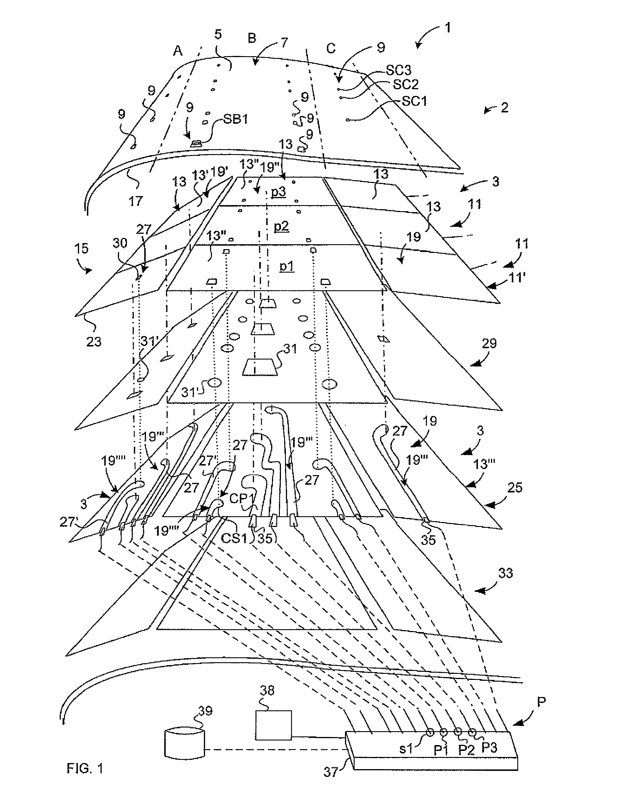
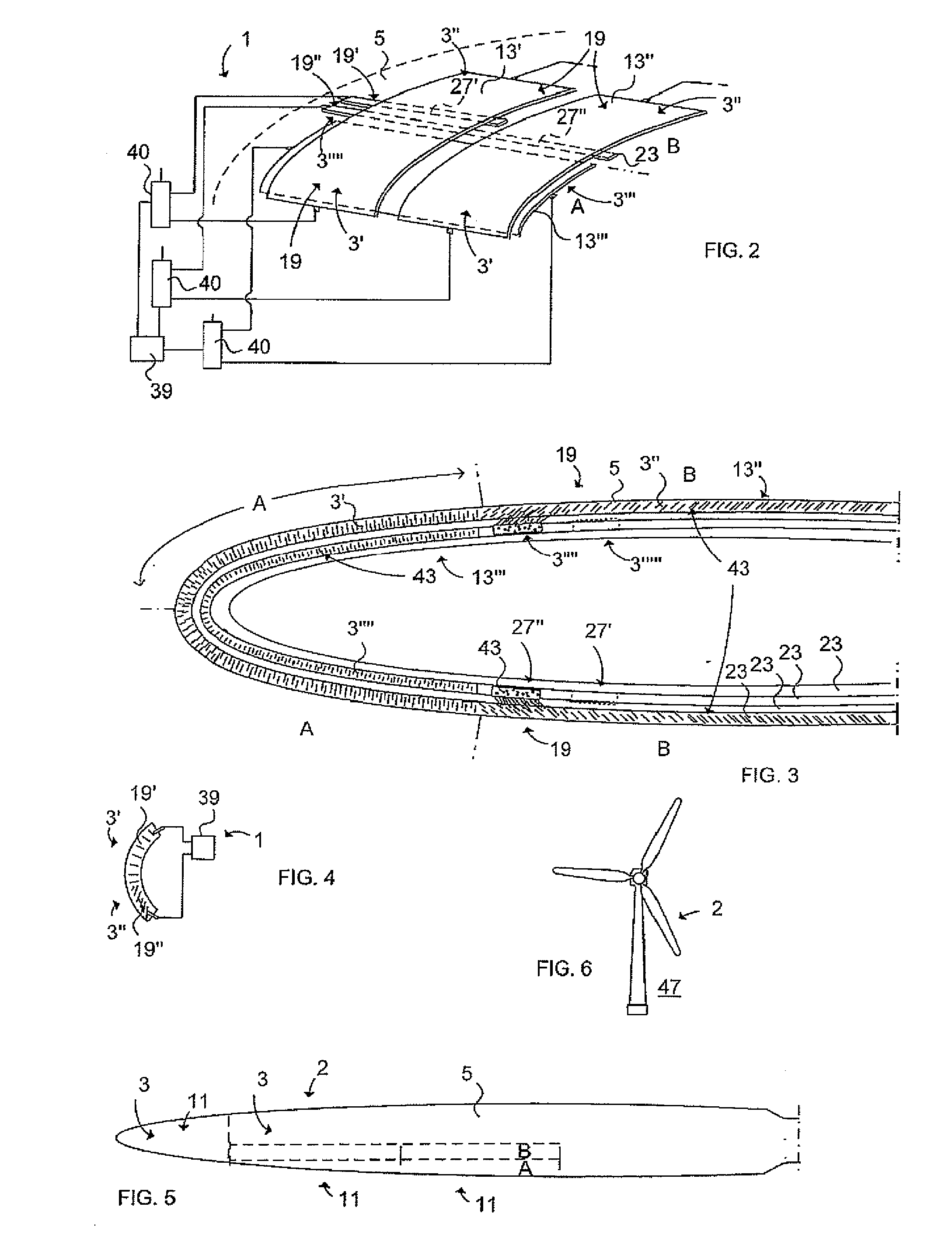
[0087]FIG. 2 illustrates schematically a de-icing / anti-icing system 1 according to a In this case the system 1 comprises five conductive structures 3′, 3″, 3′″, 3″″, 3′″″, each having a conductive nano structure 19, further explained below (see FIG. 3). A shorter heating conductor 27′ of conductive nano structure 19′ in an elongated resin layer extends to and is in contact with an upper inner heating element 13′. A longer heating conductor 27″ of conductive nano structure 19″ extends to an upper outer heating element 13″. Each of the heating element 13′, 13″ is divided in two sections, each arranged for area A and area B respectively. This is made by arranging leaning conductive nano filaments (area B) and transversal (area A) conductive nano filaments (See also FIG. 3). A control unit 39 controls the current supply (on / off) to the respective heating element 13′, 13″ via switches 40 and electrical wires. Due to the higher electric resistance of the area A conductive nano structure ...

third embodiment

[0089]FIG. 4 schematically illustrates a de-icing / anti-icing system 1 according to a wind power station. The system 1 comprises a control unit 39 controlling the current supply via electrical wires to a de-icing / anti-icing heating element including one conductive structure 3′ comprising a first conductive nano structure 19′ and another conductive structure 3″ including a second conductive nano structure 19″. The two conductive structures 3′, 3″ have different functionality and different conductive properties due to the architecture of the conductive nano structure 19′, 19″ in respective conductive structure 3′, 3″. The control unit 39 controls the energy supply to the de-icing / anti-icing heating element by regulating the current level. By means of different electric resistance achieved by different orientations of the conductive nano structures 19′, 19″, heat of different temperature will be produced by each conductive structure 3′, 3″.

[0090]FIG. 5 schematically illustrates a wind t...


PUM


Abstract

A de-icing/anti-icing system including at least two conductive structures embedded in a wind turbine blade. An outer surface is designed as an aerodynamic surface. At least one of the conductive structures is arranged adjacent the outer surface. A control unit adapted to control the energy supply to the conductive structures for generating heat to the outer surface. One conductive structure includes a first conductive nano structure. A conductive property of the conductive structure differs from a conductive property of the other conductive structure including a second conductive nano structure, for achieving different degrees of heat depending on the needed mode of the system.

Description

TECHNICAL FIELD[0001]The present invention relates to a multifunctional de-icing / anti-icing system according to the preamble of claim 1 and an article comprising an outer surface, which serves as an aerodynamic surface when the article moves relatively the air.BACKGROUND ART[0002]An article (e.g. a wind turbine blade) moving through the air may be subject for icing if specific weather conditions are present. Today aerodynamic surfaces of wind turbine blades are protected from icing by means of anti-icing and de-icing devices arranged at or beneath the aerodynamic surface. Icing is known as an undesired phenomenon, wherein a build-up of ice takes place on the aerodynamic surface.[0003]Composite or metallic structures of the article comprising the aerodynamic surface are thus formed with aerodynamic functions and are subjected to ice build-up on their outer surfaces under specific operational conditions. The ice build-up has a strong negative effect on the aerodynamic efficiency of th...

Claims


Application Information

Patent Timeline
Patent Type & Authority Applications(United States)
IPC IPC(8): F03D11/00
CPCF03D11/0025H05B3/145Y02E10/722Y02E10/721F03D11/0033H05B2214/04F03D80/30F03D80/40Y02E10/72
Inventor NORDIN, PONTUSSTRINDBERG, GOTE
Owner SAAB AB
Why Eureka
Try Eureka