Method for burying conductive mesh in transparent electrode

Active Publication Date: 2013-02-07
KOREA INST OF MASCH & MATERIALS
View PDF35 Cites 9 Cited by
  • Summary
  • Abstract
  • Description
  • Claims
  • Application Information

AI Technical Summary

Benefits of technology

[0021]According to an embodiment of the present invention, the contact performance of the transparent electrode is improved because the

Problems solved by technology

Although ITO, having superior general properties, is mainly applied to the process to date, indium oxide (In2O3) is produced as a by-product in a zinc (Zn) mine, and problems of instable supply and unmet demand arise.
Further, the ITO film is not flexible and thus cannot be used as a flexible material for a polymer substrate, and furthe

Method used


Image

  • Method for burying conductive mesh in transparent electrode
  • Method for burying conductive mesh in transparent electrode
  • Method for burying conductive mesh in transparent electrode

Examples


exemplary embodiment 1

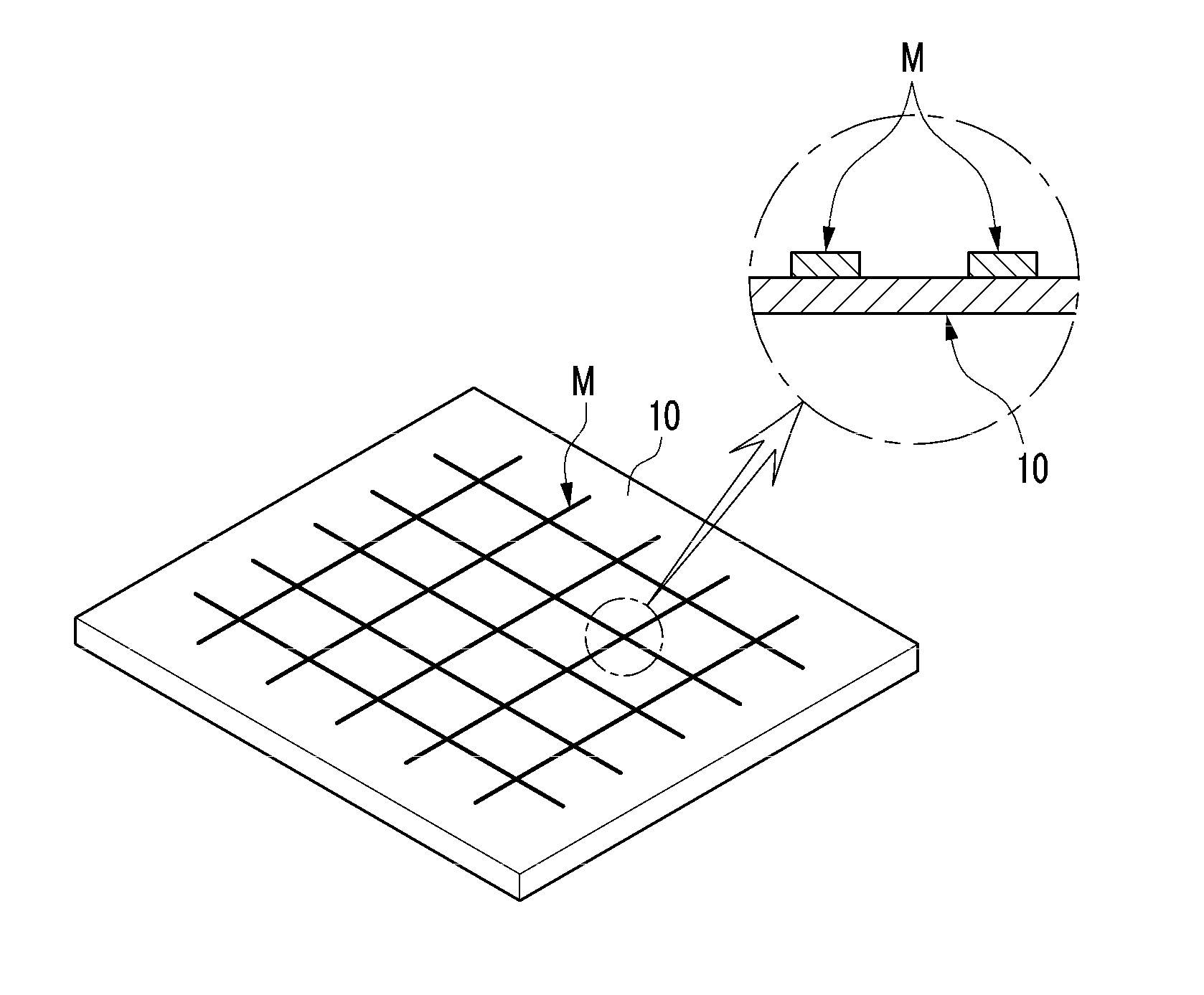
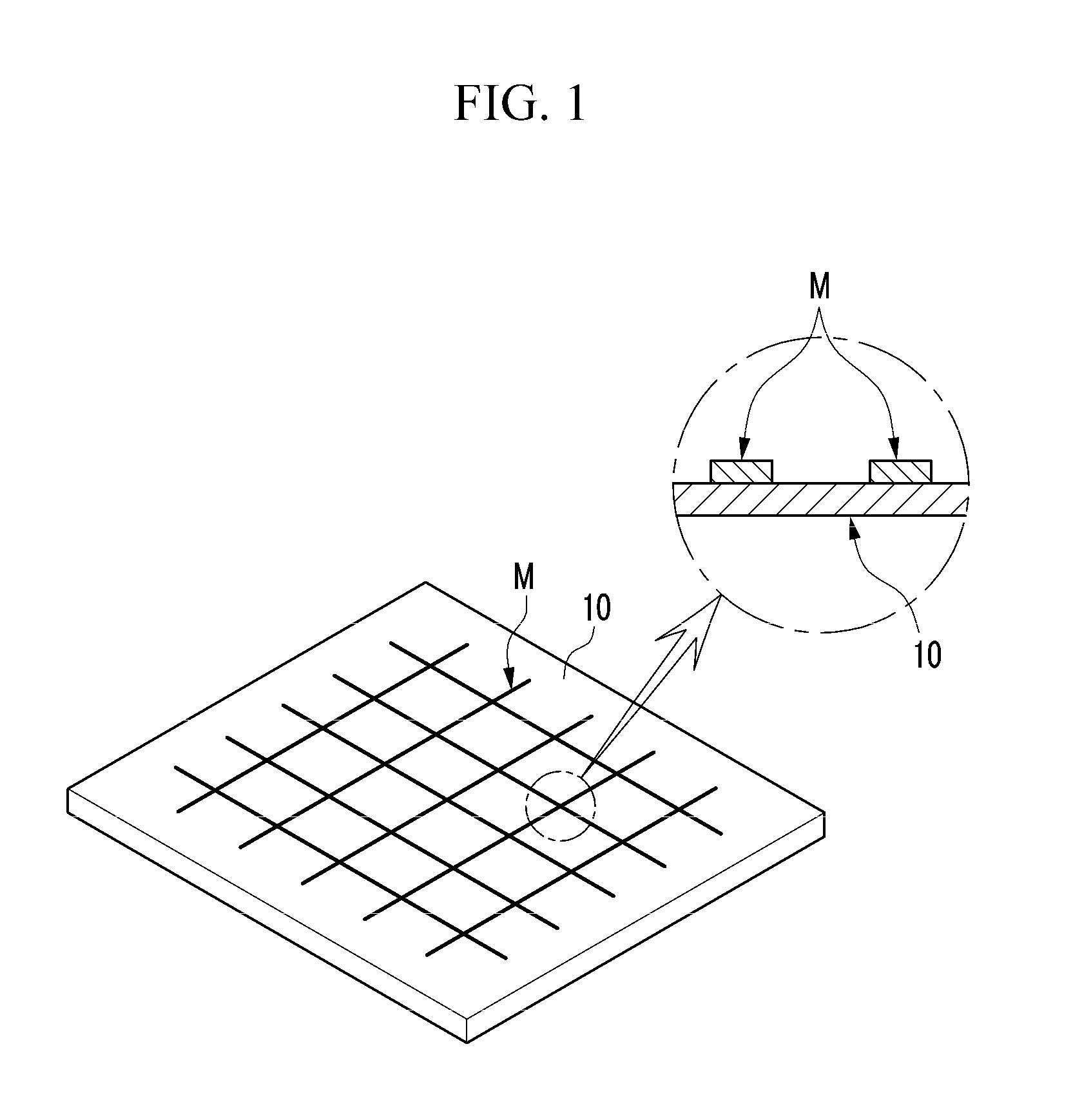
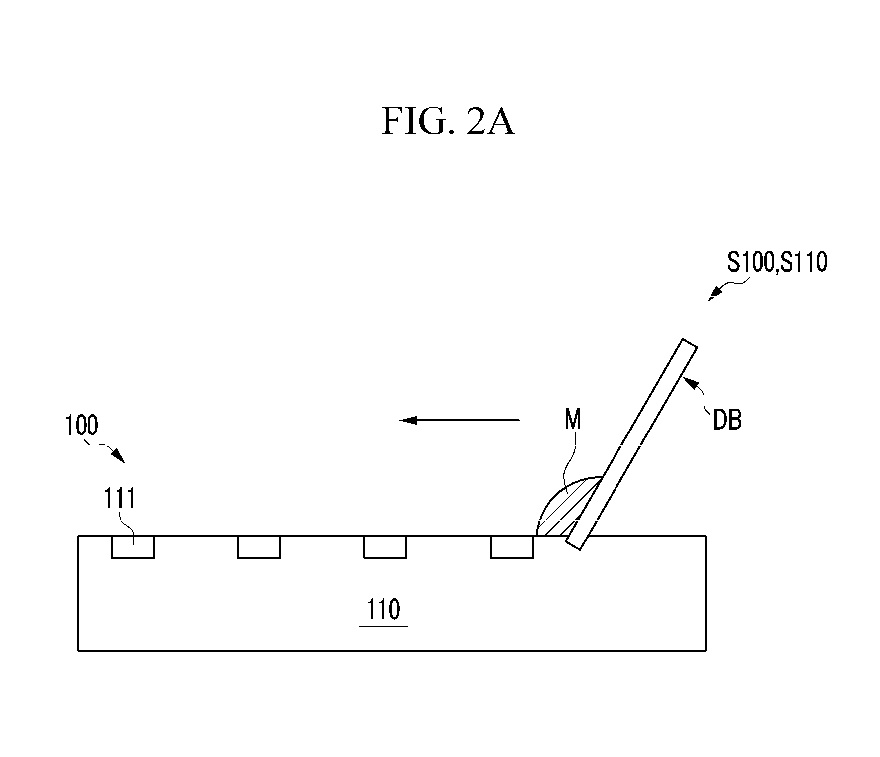
[0039]As shown in FIGS. 2A to 2E, the embodiment of the present invention involves a method S100 for burying a conductive mesh M in a transparent electrode E by using a mesh burying device 100 including a bed 110 with a plurality of recesses 111, serving as molds of the conductive mesh M buried in the transparent electrode E and forming a mesh form by crossing each other, and a first transfer unit 120 made of PDMS adapted to be in contact with the bed 110.

[0040]To this end, first of all, the step S110 (hereinafter, referred to as the eleventh step) of filling a liquid conductive mesh M in the recesses 111 of the bed 110 is carried out. (see FIG. 2A)

[0041]In the eleventh step S110, a liquid conductive mesh may be poured onto the bed 110 by a dispenser (not shown), and then the liquid conductive mesh M may be filled in the recesses 111 of the bed 110 by using a doctor blade DB.

[0042]Afterwards, the step S120 (hereinafter, referred to as the twelfth step) of bringing the first transfer...

exemplary embodiment 2

[0056]As shown in FIGS. 3A to 3I, the embodiment of the present invention involves a method S200 for burying a conductive mesh M in a transparent electrode E by using a mesh burying device 200 including a bed 210 with a plurality of recesses 211, serving as molds of the conductive mesh M buried in the transparent electrode E and forming a mesh form by crossing each other, a first transfer unit 220 made of PDMS adapted to be in contact with the bed 210, and a second transfer unit 230 made of PDMS adapted to be in contact with the first transfer unit 220, and having a lower contact force than the first transfer unit 220.

[0057]To this end, first of all, the step S210 (hereinafter, referred to as the twenty-first step) of filling a liquid conductive mesh M in the recesses 211 of the bed 210 is carried out. (see FIG. 3A)

[0058]The twenty-first step S210 is identical to the eleventh step S110 of Exemplary Embodiment 1, so redundant description will be omitted.

[0059]After carrying out the t...

exemplary embodiment 3

[0070]As shown in FIG. 4, the embodiment of the present invention provides a method S300 of burying a conductive mesh M in a transparent electrode E by a gravure offset printing machine 300.

[0071]That is, the embodiment of the present invention provides a method S300 of burying a conductive mesh M in a transparent electrode E by a gravure offset printing machine 300, the gravure offset printing machine 300 including a pattern roller 310 with a plurality of recesses 311, serving as molds of the conductive mesh M buried in the transparent electrode E and forming a mesh form by crossing each other, a blanket roller 320 having a blanket 321 made of PDMS adapted to be in contact with the pattern roller 310, and an impression roller 330 to be brought into contact with the blanket roller 320, with a substrate S interposed therebetween.

[0072]To this end, first of all, the step S310 (hereinafter, referred to as the thirty-first step) of filling a liquid conductive mesh M in the recesses 311 ...


PUM

PropertyMeasurementUnit
Electrical conductoraaaaaaaaaa
Transparencyaaaaaaaaaa

Abstract

The present invention relates to a method for burying a conductive mesh in a transparent electrode, and more particularly, to a method which prevents a conductive mesh from protruding from a transparent electrode by burying the conductive mesh in the transparent electrode.

Description

CROSS-REFERENCE TO RELATED APPLICATION[0001]This application claims priority to and the benefit of Korean Patent Application No. 10-2011-007681 7 filed in the Korean Intellectual Property Office on Aug. 2, 2011, the entire contents of which are incorporated herein by reference.BACKGROUND OF THE INVENTION[0002](a) Field of the Invention[0003]The present invention relates to a method for burying a conductive mesh in a transparent electrode, and more particularly, to a method which prevents a conductive mesh from protruding from a transparent electrode by burying the conductive mesh in the transparent electrode.[0004](b) Description of the Related Art[0005]Generally, a transparent conductive film is used for plasma display panels (PDPs), liquid crystal displays (LCDs), light emitting diodes (LEDs), organic electroluminescent devices (OLEDs), touch panels, solar cells, etc.[0006]Because the transparent electrode has high conductivity and high transmittance in the visible light range, it...

Claims


Application Information

Patent Timeline
IPC IPC(8): H01R43/04
CPCG06F3/044G06F3/045H01R43/04H05K3/1275Y10T29/49217H05K2203/0113H05K2203/0534G02F1/13439H01L31/022466H05K2201/09681G06F2203/04112G06F3/0412G06F2203/04111H01B13/0026
Inventor LEE, TAIK MINKIM, IN YOUNGJO, JEONG DAIKIM, DONG-SOO
Owner KOREA INST OF MASCH & MATERIALS
Why Eureka
Try Eureka