Control method of magnetic solenoid valve, control method of electromagnetically controlled inlet valve of high pressure fuel pump, and control device for electromagnetic actuator of electromagnetically controlled inlet valve

a technology of electromagnetic actuator and electromagnetic solenoid valve, which is applied in the direction of electric control, piston pumps, positive displacement liquid engines, etc., to achieve the effects of reducing noise caused by impingement, consuming current, and reducing consumption curren

Active Publication Date: 2013-02-07
HITACHI ASTEMO LTD
View PDF11 Cites 33 Cited by
  • Summary
  • Abstract
  • Description
  • Claims
  • Application Information

AI Technical Summary

Benefits of technology

[0009]Due to such a constitution, a consumed current (in a compression stroke of a pump, for example) can be reduced. Further, by supplying the second current (in a suction stroke of the pump, for example), a speed at which the plunger rod moves in the valve opening direction is lowered (without pulling back the plunger rod to the valve closed position) so that noises caused by the impingement can be reduced.
[0010]It is also desirable that the limited current supply period includes a hold current period where the plunger is held at the valve closed position and a zero current period which succeeds the hold current period. Due to the provision of such periods, a consumed current can be further reduced. Here, an inlet valve is maintained in a valve closing state due to a back pressure of a pressurizing chamber and hence, there is no possibility that a valve opening operation is performed by the plunger rod during the zero current region.
[0011]In applying a control method of a magnetic solenoid valve to a high pressure fuel pump, it is further desirable that, at timing where a plunger piston almost reaches the top dead center, an electric current supplied to an electromagnetic actuator is controlled to zero. Here, the inlet valve is held at a valve closed position by a pressurized fuel pressure. On the other hand, the plunger rod moves in the valve opening direction until the plunger rod engages with the inlet valve. Due to such a control, in a succeeding suction stroke, a distance that the plunger rod moves becomes short so that potential energy of impingement movement can be lowered. Eventually, power consumption can be reduced.

Problems solved by technology

A drive sound of an engine is tranquil when a vehicle is in an idling state and hence, noises generated by such an impingement cause a serious problem.

Method used


Image

  • Control method of magnetic solenoid valve, control method of electromagnetically controlled inlet valve of high pressure fuel pump, and control device for electromagnetic actuator of electromagnetically controlled inlet valve
  • Control method of magnetic solenoid valve, control method of electromagnetically controlled inlet valve of high pressure fuel pump, and control device for electromagnetic actuator of electromagnetically controlled inlet valve
  • Control method of magnetic solenoid valve, control method of electromagnetically controlled inlet valve of high pressure fuel pump, and control device for electromagnetic actuator of electromagnetically controlled inlet valve

Examples


first embodiment

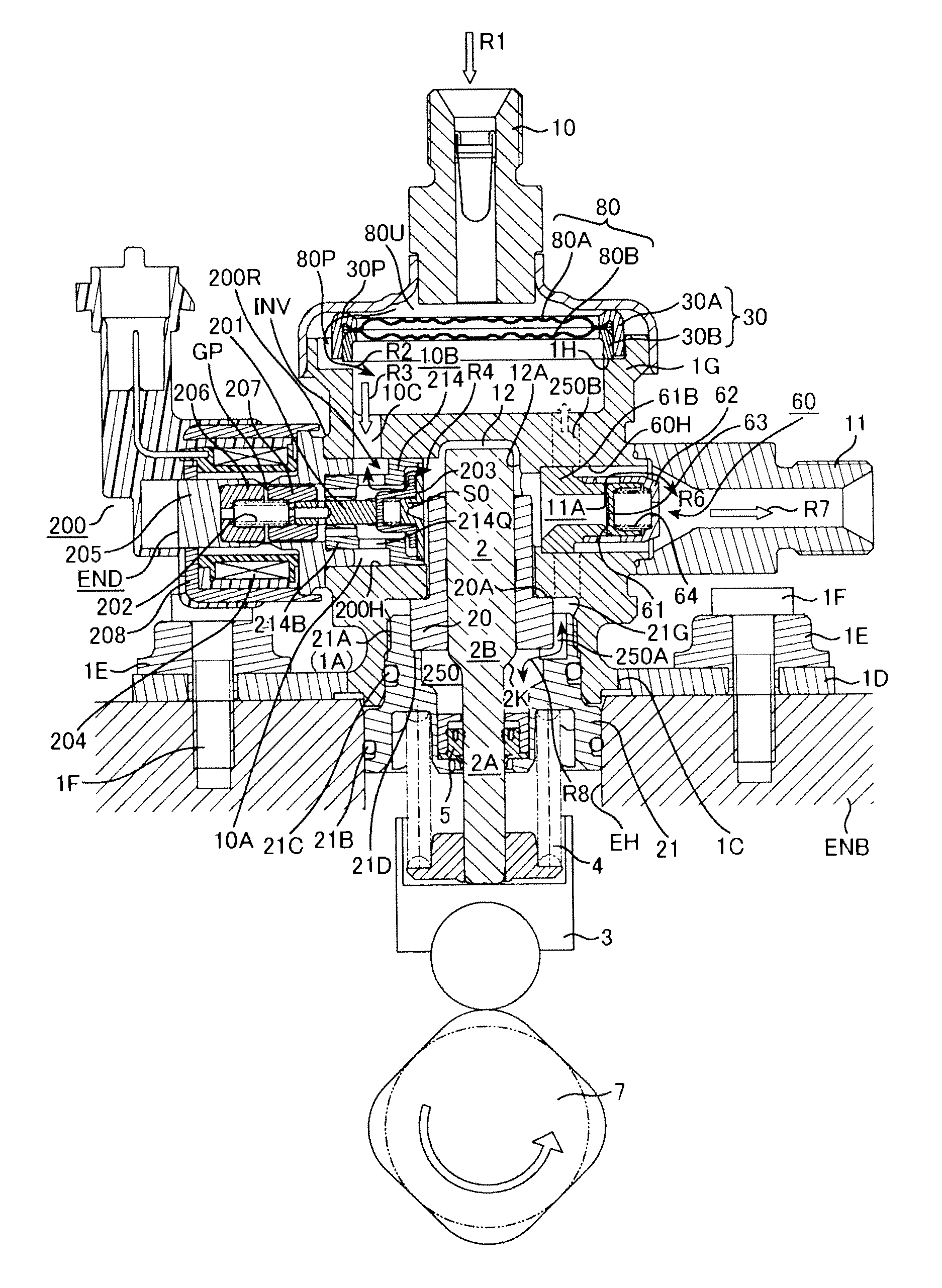
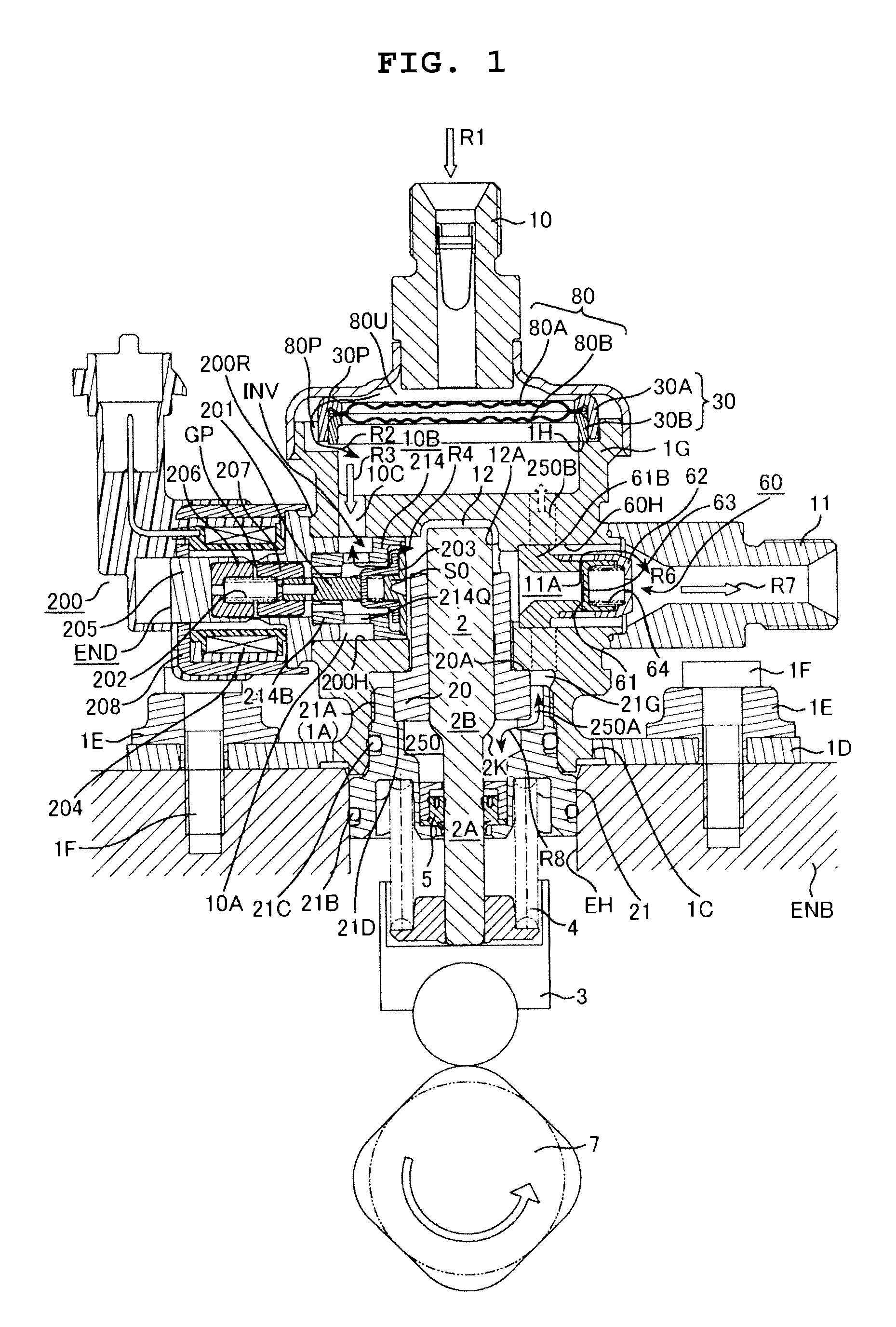
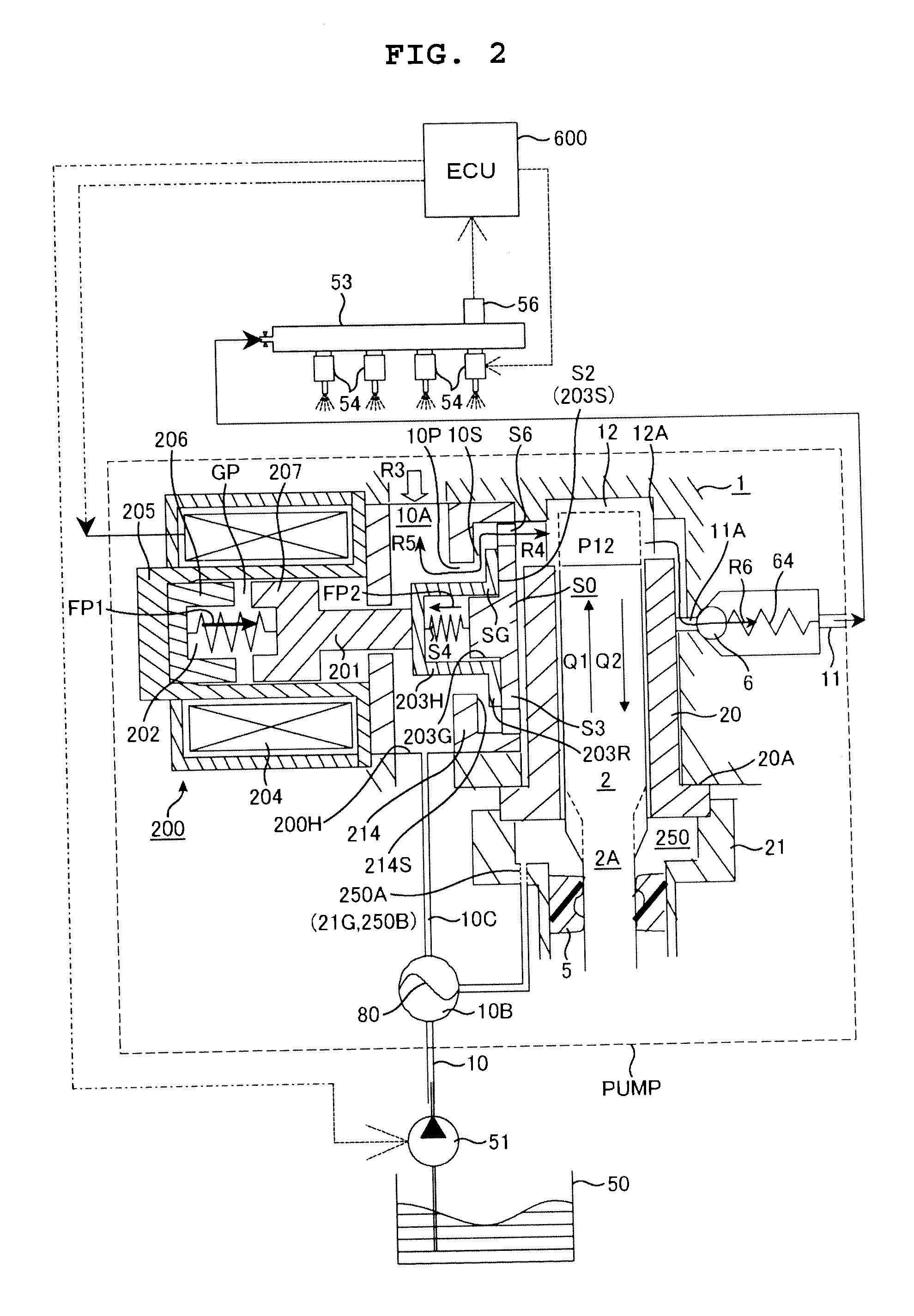
[0023]The first embodiment of a high pressure fuel pump in which the present invention is carried out is explained in conjunction with FIG. 1 to FIG. 5. Symbols cannot be given to detailed parts in FIG. 1 and hence, symbols used in the explanation which are not described in FIG. 1 are described in enlarged views including FIG. 2 and succeeding drawings.

[0024]A recessed portion 12A which forms a bottomed cylindrical space with one end open is formed on a pump housing 1, and a cylinder 20 is inserted into the recessed portion 12A from an open end side. A gap between an outer periphery of the cylinder 20 and the pump housing 1 is sealed by a pressure contact portion 20A. A piston plunger 2 is slidably fitted into the cylinder 20 and hence, a gap between an inner peripheral surface of the cylinder 20 and an outer peripheral surface of the piston plunger 2 is sealed by fuel which intrudes between both slide fitting surfaces. As a result, a pressurizing chamber 12 is formed between a dist...

second embodiment

[0086]FIG. 7 shows a second embodiment. A high pressure fuel pump of this embodiment is equal to the high pressure fuel pump of the first embodiment in constitution. In the second embodiment, a current supply period is switched to a limited current supply period while a plunger rod 201 moves in the valve closing direction. By lowering a current value to, for example, a value close to a holding current during the movement of the plunger rod 201, a magnetic attraction force is reduced so that a moving speed of the plunger rod 201 is lowered compared to a moving speed of the plunger rod 201 in the first embodiment. As a result, noises which are generated when an anchor 207 impinges on a fixed core 206 are reduced.

[0087]To consider a case where only a limited current is given without supplying a first current, a magnetic attraction force larger than a biasing force of a plunger rod biasing spring is not generated thus giving rise to a possibility that the plunger rod 201 cannot be moved...

third embodiment

[0091]FIG. 8 shows a third embodiment. In this embodiment, a high current is initially given in a 1st current supply period and, thereafter, the current value is lowered. Due to such an operation, the movement of a plunger rod 201 can be surely started by giving a high current initially. Further, a period during which a high current value is given can be shortened and hence, a heating value of a solenoid is not largely increased. This embodiment is advantageously applicable to a case where a current value cannot be accurately controlled or a case where it is necessary to take a large margin in an operational current.

[0092]In this embodiment, although a current value in the 1st current supply period is not a fixed value, a peak current never fails to become larger than a current value necessary for an operation of attracting a plunger rod 201 (an electric current which makes a magnetic attraction force larger than a biasing force of a plunger rod biasing spring).

[0093]In this embodim...


PUM


Abstract

In an electromagnetically controlled inlet valve actuator provided to a high pressure fuel pump, an impinging sound which is generated at the time of operating the mechanism is reduced. In a high pressure fuel pump provided with an electromagnetically controlled inlet valve (operated by way of a plunger rod), a current supply period includes a 1st current supply period for performing an operation of attracting the plunger rod in a valve closing direction, a 2nd current supply period for alleviating a speed at which the plunger rod moves in a valve opening direction, and a limited current supply period disposed between the 1st current supply period and the 2nd current supply period in the form of spanning a pump top dead center.

Description

BACKGROUND OF THE INVENTION[0001]1. Field of the Invention[0002]The present invention relates to a control method of a magnetic solenoid valve used in an electromagnetically controlled inlet valve which adjusts a discharge amount of fuel by adjusting an amount of fuel which is discharged (spilled) from an inlet passage out of fuel sucked into a high pressure fuel pump, a control method of an electromagnetically controlled inlet valve of a high pressure fuel pump which includes a magnetic solenoid valve driven by the method as an inlet valve, and a control device of an electromagnetic actuator of an electromagnetically controlled inlet valve.[0003]2. Description of the Related Art[0004]As a related art pertaining to the field of the present invention, there has been known a device described in JP-A-2009-203987 (patent document 1). In this publication, there is the description that an amount of fuel which is fed under high pressure from a high pressure fuel pump is adjusted by control...

Claims


Application Information

Patent Timeline
Patent Type & Authority Applications(United States)
IPC IPC(8): F16K31/02
CPCF02D41/20F02D41/3082F02D2041/2058F02D2041/2037F02D2041/2027Y10T137/0318F02D41/3845F04B49/243F04B7/0053F04B17/05F04B49/065
Inventor TOKUO, KENICHIROUSUI, SATOSHISUGANAMI, MASAYUKIARITOMI, SHUNSUKE
Owner HITACHI ASTEMO LTD
Why Eureka
Try Eureka