Fuel Cell System and Method of Operating the fuel Cell System

a fuel cell and system technology, applied in the field of fuel cell systems, can solve the problems of wasteful and uneconomical heat energy consumption, large size complicated fuel cell system, etc., and achieve the effect of improving reliability and durability, stably stopping the operation of the fuel cell system, and advantageously prolonging the product li

Inactive Publication Date: 2013-02-07
HONDA MOTOR CO LTD
View PDF2 Cites 2 Cited by
  • Summary
  • Abstract
  • Description
  • Claims
  • Application Information

AI Technical Summary

Benefits of technology

[0010]The present invention has been made to solve the problem of this type, and an object of the present invention is to provide a fuel cell system and a method of operating the fuel cell system in which it is possible to inhibit oxidation and carbon precipitation (coking) of the MEA and reforming catalyst, and reduce energy consumption as much as possible, without requiring any additional purge gas supply system.
[0016]In the present invention, at the time of starting operation of the fuel cell system, the raw fuel is temporarily supplied to the electrode surface of the anode to discharge the air remaining in the fuel line. Therefore, the atmosphere in the fuel line is a reducing atmosphere in the presence of the raw fuel. At the time of raising the temperature of the fuel cell stack, even if the MEA and the reforming catalyst are in the active state, it is possible to suitably inhibit oxidation of the MEA and the reforming catalyst. Accordingly, improvement in the durability is achieved, and the product life is prolonged advantageously.
[0017]Further, at least based on any of the temperature of the fuel cell stack and the temperature of the evaporator, i.e., in the temperature range where the water vapor can be produced stably, and water vapor oxidation of the electrolyte electrode assembly does not occur easily, the water vapor is supplied to the electrode surface of the anode. After it is confirmed that the water vapor is produced stably, the raw fuel and the water are supplied to the evaporator to supply the fuel gas to the electrode surface of the anode. Thus, it is possible to start operation of the fuel cell system stably. Further, degradation of the MEA and the reforming catalyst is prevented, improvement in the reliability and durability is achieved, and the product life is prolonged advantageously.
[0018]Thus, it is possible to start operation of the fuel cell system simply by setting the timings of supplying and stopping the raw fuel, the water vapor and the fuel gas without requiring any purge gas supply system additionally. Accordingly, a simple fuel cell system can be provided at low cost easily.
[0020]After the stop of the water supply is confirmed, i.e., after it is confirmed that only the raw fuel is supplied, the supply of the raw fuel to the electrode surface of the anode is stopped. Accordingly, it is possible to stably stop operation of the fuel cell system without causing water condensation or the like. Further, degradation of the MEA and the reforming catalyst is inhibited. Improvement in the reliability and durability is achieved, and the product life is prolonged advantageously.
[0021]Thus, in the fuel cell system, by simply setting the timings of supplying and stopping the raw fuel, the water vapor and the fuel gas, it is possible to stop operation of the fuel cell system without requiring any purging gas system additionally. Accordingly, the fuel cell system is simplified, and produced at low cost easily.

Problems solved by technology

Therefore, the overall size of the fuel cell system becomes large, and the fuel cell system is complicated.
For this purpose, heat energy is consumed wastefully and uneconomically.
Moreover, the system is complicated.
Further, in Japanese Laid-Open Patent Publication No. 2006-294508, the technique is only used at the time of stopping power generation in the fuel cell, and no solution is provided for degradation such as oxidation or the like of the MEA and reforming catalyst at the time of starting operation of the fuel cell.

Method used


Image

  • Fuel Cell System and Method of Operating the fuel Cell System
  • Fuel Cell System and Method of Operating the fuel Cell System
  • Fuel Cell System and Method of Operating the fuel Cell System

Examples


Embodiment Construction

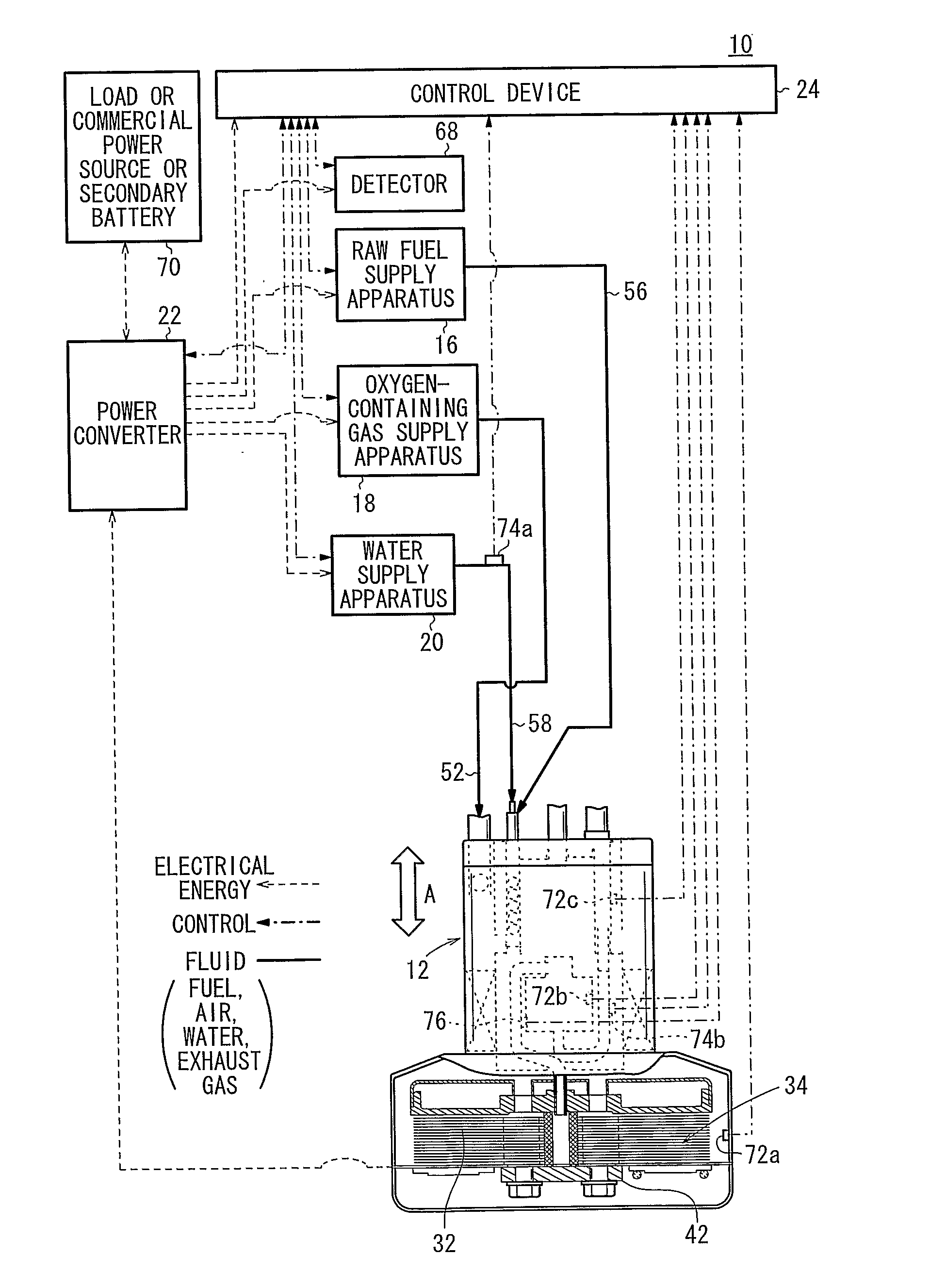
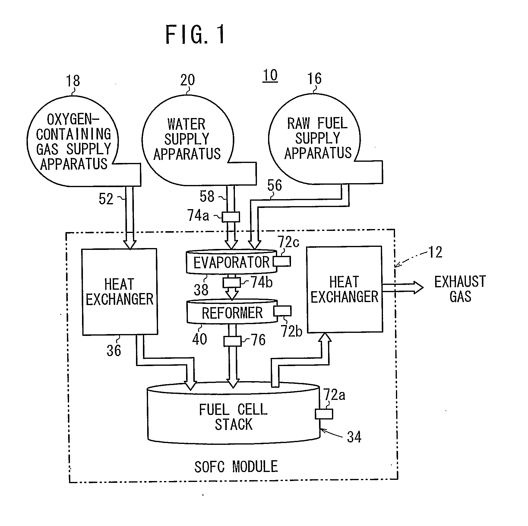
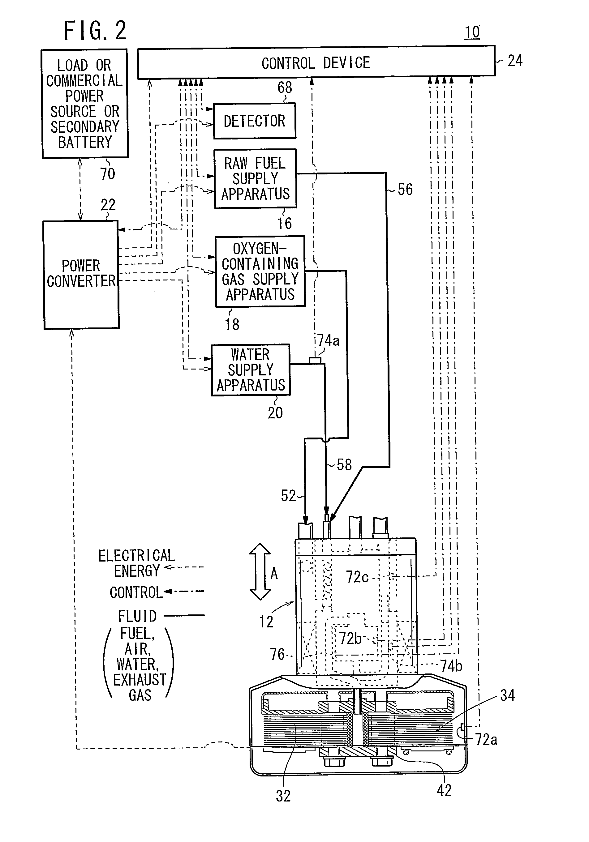
[0032]FIG. 1 is a diagram schematically showing structure of a mechanical circuit of a fuel cell system 10 according to an embodiment of the present invention, and FIG. 2 is a circuit diagram showing the fuel cell system 10.

[0033]The fuel cell system 10 is used in various applications, including stationary and mobile applications. For example, the fuel cell system 10 is mounted on a vehicle. The fuel cell system 10 includes a fuel cell module (SOFC module) 12 for generating electrical energy in power generation by electrochemical reactions of a fuel gas (hydrogen gas) and an oxygen-containing gas (air), a raw fuel supply apparatus (including a fuel gas pump) 16 for supplying a raw fuel (e.g., city gas) to the fuel cell module 12, an oxygen-containing gas supply apparatus (including an air pump) 18 for supplying an oxygen-containing gas to the fuel cell module 12, a water supply apparatus (including a water pump) 20 for supplying water to the fuel cell module 12, a power converter 22...


PUM

PropertyMeasurementUnit
operating temperatureaaaaaaaaaa
molar ratioaaaaaaaaaa

Abstract

A method of operating a fuel cell system includes the steps of temporarily supplying a raw fuel to an electrode surface of an anode at the time of starting operation of the fuel cell system, supplying water vapor to the electrode surface of the anode at least based on any of the temperature of a fuel cell stack and the temperature of an evaporator after stopping the supply of the raw fuel, and supplying a fuel gas to the electrode surface of the anode by supplying the raw fuel and the water to the evaporator at least based on any of detection results of the pressure of the water supplied to the evaporator, the flow rate of the water supplied to the evaporator), the pressure of the water vapor discharged from the evaporator, and the flow rate of the water vapor discharged from the evaporator.

Description

TECHNICAL FIELD [0001]The present invention relates to a fuel cell system including a fuel cell stack, an evaporator, a reformer, and a control device. The fuel cell stack is formed by stacking a plurality of fuel cells. Each of the fuel cells is formed by stacking an electrolyte electrode assembly and a separator. The, electrolyte electrode assembly includes an anode, a cathode, and an electrolyte interposed between the anode and the cathode. The evaporator produces a mixed fuel of a raw fuel chiefly containing hydrocarbon and water vapor obtained by evaporating water. The reformer produces a fuel gas by reforming the mixed fuel. Further, the present invention relates to a method of operating the fuel cell system.BACKGROUND ART[0002]Typically, a solid oxide fuel cell (SOFC) employs an electrolyte of ion-conductive solid oxide such as stabilized zirconia. The electrolyte is interposed between an anode and a cathode to form an electrolyte electrode assembly (MEA). The electrolyte ele...

Claims


Application Information

Patent Timeline
Patent Type & Authority Applications(United States)
IPC IPC(8): H01M8/06
CPCH01M8/04007H01M8/04223H01M8/04268H01M8/04365H01M8/04417H01M8/04432Y02E60/525H01M8/04731H01M8/04835H01M8/0612H01M8/2425H01M2008/1293Y02E60/50H01M8/04462H01M8/04225H01M8/04302
Inventor DAN, KOJI
Owner HONDA MOTOR CO LTD
Why Eureka
Try Eureka