Semiconductor device and method of making the same

a technology of semiconductor devices and semiconductor devices, applied in the direction of semiconductor devices, electrical devices, transistors, etc., to achieve the effects of preventing residual etching solution/chemical solvent adversely affecting the semiconductor device, reducing the damage to the formed structure, and improving the efficiency and performance of the semiconductor devi

Active Publication Date: 2013-02-14
UNITED MICROELECTRONICS CORP
View PDF8 Cites 396 Cited by
  • Summary
  • Abstract
  • Description
  • Claims
  • Application Information

AI Technical Summary

Benefits of technology

[0009]The present invention combines an ion implantation process with a selective epitaxial growth (SEG) process for fabricating the fin structures having the strained silicon epitaxial layer. This method omits the etching/pre-clean steps in the conventional process for fabricating the epitaxial layer; accordingly, the damage to the formed structures can be...

Problems solved by technology

To meet the design trends with respect to high integration, high performance, low power consumption, and the demand of products, ...

Method used


Image

  • Semiconductor device and method of making the same
  • Semiconductor device and method of making the same
  • Semiconductor device and method of making the same

Examples


first exemplary embodiment

The First Exemplary Embodiment

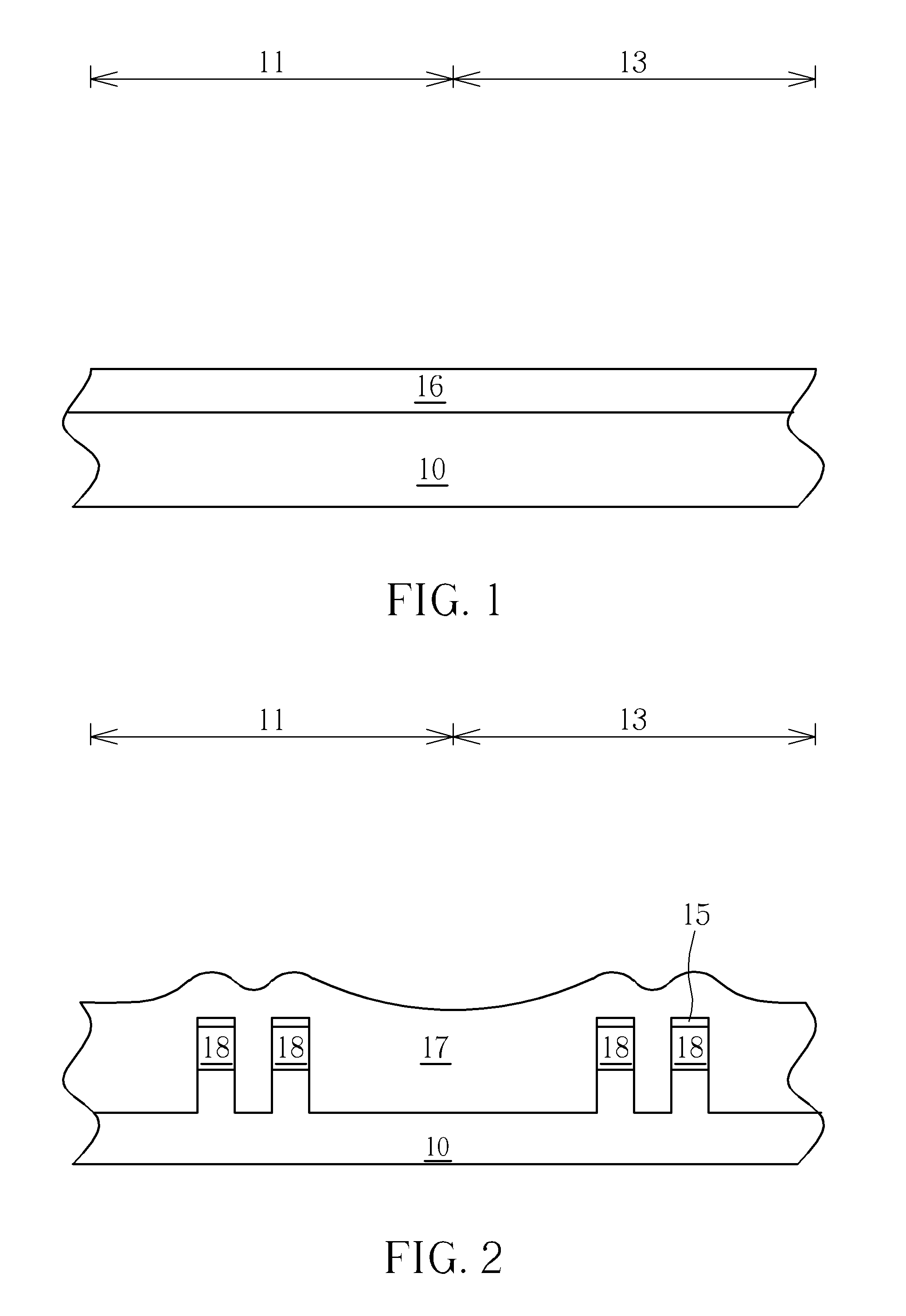
[0018]The entirely formed semiconductor layer 16 includes (Si(1-x-y)GexCy), and the ratio of y to x is larger than 0.1, i.e. y>0.1x. The semiconductor layer 16 has an original tensile stress. In this exemplary embodiment, a patterned mask (not shown) is used to cover the NMOS region 11 and expose the PMOS region 13. Furthermore, an ion implantation process with the dopant of 4A group elements including Ge is performed for modifying the semiconductor layer 16 in the PMOS region 13. Consequently, the semiconductor layer 16 in the PMOS region 13 may be changed to include (Si(1-x-y)GexCy) and y<0.1x; that is, the strained silicon epitaxial layer will have a compressive stress instead of the tensile stress. Afterwards, the patterned mask is removed.

second exemplary embodiment

The Second Exemplary Embodiment

[0019]The entirely formed semiconductor layer 16 includes (Si(1-x-y)GexCy), and the ratio of y to x is smaller than 0.1, i.e. y16 has an original compressive stress. In this exemplary embodiment, a patterned mask (not shown) is used to cover the PMOS region 13 and expose the NMOS region 11. Furthermore, an ion implantation process with the dopant of 4A group elements including C is performed for modifying the semiconductor layer 16 in the NMOS region 11. Consequently, the semiconductor layer 16 in the NMOS region 11 may be changed to include (Si(1-x-y)GexCy) and y>0.1x; that is, the strained silicon epitaxial layer will have a tensile stress instead of the compressive stress. Afterwards, the patterned mask is removed.

third exemplary embodiment

The Third Exemplary Embodiment

[0020]The entirely formed semiconductor layer 16 includes (Si(1-x-y)Gex), i.e. the semiconductor layer 16 has original compressive stress. In this exemplary embodiment, a patterned mask (not shown) is used to cover the PMOS region 13 and expose the NMOS region 11. Furthermore, an ion implantation process with the dopant of 4A group elements including C is performed for modifying the semiconductor layer 16 in the NMOS region 11. Consequently, the semiconductor layer 16 in the NMOS region 11 may be changed to include (Si(1-x-y)GexCy) and y>0.1x; that is, the strained silicon epitaxial layer will have a tensile stress instead of the compressive stress. Afterwards, the patterned mask is removed.


PUM


Abstract

A semiconductor device includes a semiconductor substrate, at least a first fin structure, at least a second fin structure, a first gate, a second gate, a first source/drain region and a second source/drain region. The semiconductor substrate has at least a first active region to dispose the first fin structure and at least a second active region to dispose the second fin structure. The first/second fin structure partially overlapped by the first/second gate has a first/second stress, and the first stress and the second stress are different from each other. The first/second source/drain region is disposed in the first/second fin structure at two sides of the first/second gate.

Description

BACKGROUND OF THE INVENTION[0001]1. Field of the Invention[0002]The present invention relates to a semiconductor device and a method for making the same, and more particularly, to a semiconductor device including a channel region having a strained silicon epitaxial layer, and a method for making the same.[0003]2. Description of the Prior Art[0004]With the trend in the industry being towards scaling down the size of metal oxide semiconductor transistors (MOS), three-dimensional or non-planar transistor technology such as multiple gate Field effect transistor (multiple gate FET) technology has been developed to replace the planar MOS transistor. The three-dimensional structure of a multiple gate FET increases the overlapping area between the gate and the fin structure of the silicon substrate, and accordingly, the channel region is more effectively controlled. The drain-induced barrier lowering (DIBL) effect and short channel effect is therefore reduced. In addition, the channel regio...

Claims


Application Information

Patent Timeline
IPC IPC(8): H01L27/092H01L21/782H01L27/12H01L21/8238
CPCH01L21/823821H01L21/845H01L29/1054H01L27/1211H01L27/0924H01L29/165
Inventor TSAI, TENG-CHUNWU, CHUN-YUANLIU, CHIH-CHIENCHIEN, CHIN-CHENGLIN, CHIN-FU
Owner UNITED MICROELECTRONICS CORP
Why Eureka
Try Eureka