Inverter-driven dynamo electric machine and system, bearing, and end bracket for same

Inactive Publication Date: 2013-02-14
HITACHI LTD
View PDF5 Cites 21 Cited by
  • Summary
  • Abstract
  • Description
  • Claims
  • Application Information

AI Technical Summary

Benefits of technology

[0023]The present embodiments provide an inverter-driven dynamo electric machine, a system, bearing, and end bracket for the same havi

Problems solved by technology

However, in the dynamo electric machine, there arise various problems such as bearing electric corrosion, insulation, an

Method used


Image

  • Inverter-driven dynamo electric machine and system, bearing, and end bracket for same
  • Inverter-driven dynamo electric machine and system, bearing, and end bracket for same
  • Inverter-driven dynamo electric machine and system, bearing, and end bracket for same

Examples


first embodiment

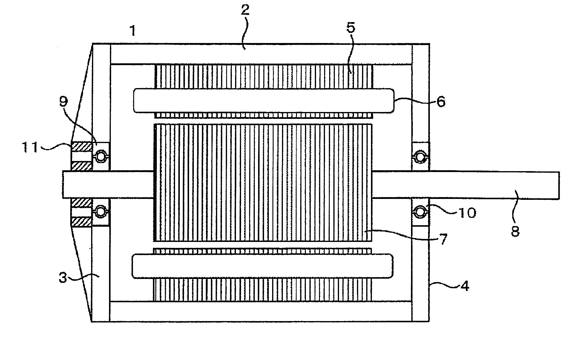
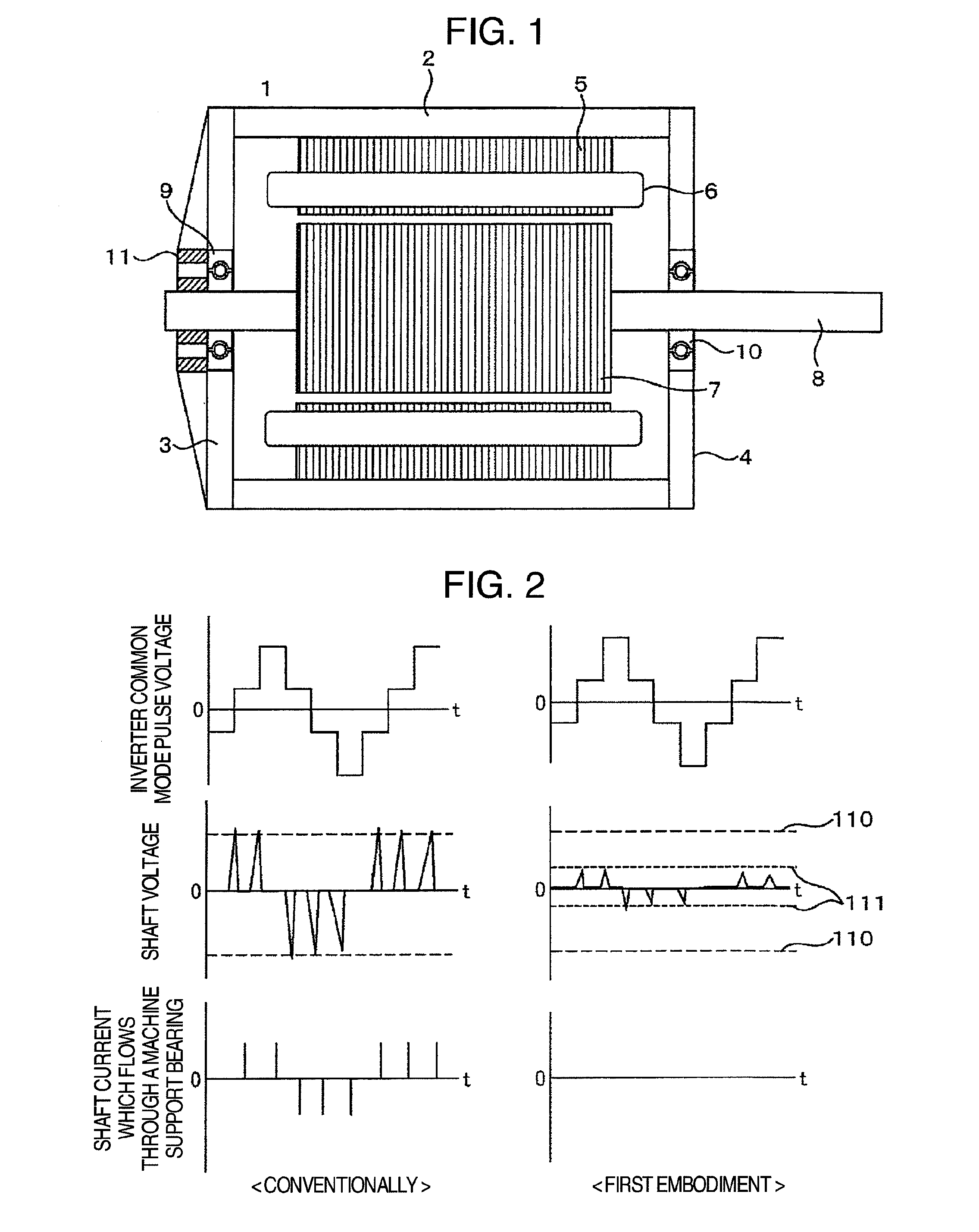
[0047]FIG. 1 illustrates a dynamo electric machine according to a first embodiment. The dynamo electric machine 1 includes a stator 5 storing a stator winding 6 and a rotor 7 rotating according to a rotating magnetic field. These units are stored in a housing 2 and end brackets 3 and 4. A shaft 8 of the rotor 7 is mechanically supported by machine support bearings 9 and 10 attached to the end brackets 3 and 4. Since the machine support bearings 9 and 10 mechanically support the shaft 8 of the rotor 7 radially and axially, a mechanical stress is not applied to an electric discharge bearing 11 provided on the end bracket 3 of a non-load side.

[0048]On the other hand, for the electric discharge bearing, there is used grease having a dielectric breakdown voltage lower than that to the machine support bearings 9 and 10, preferably, grease which is low by 0.1 V or more in the range of the rotation number to be used. Before broken dielectrically in the machine support bearing, an oil film i...

second embodiment

[0056]FIG. 12 illustrates a dynamo electric machine according to a second embodiment. In the first embodiment, the electric discharge bearing is provided in the end bracket of the non-load side; however, the electric discharge bearing is provided in the end bracket of the load side in the second embodiment. Specifically, the dynamo electric machine 121 includes a stator 125 storing a stator winding 126 and a rotor 127 rotating according to a rotating magnetic field. The above-described units are stored in a housing 122 and the end brackets 123 and 124. A shaft 128 of the rotor 127 is mechanically supported by machine support bearings 129 and 1210 attached to the end brackets 123 and 124. Since the machine support bearings 129 and 1210 mechanically support the shaft 128 of the rotor 127 radially and axially, a mechanical stress is not applied to an electric discharge bearing 1211 provided on the end bracket 124 of the load side.

[0057]Since a mechanical stress is not applied to the el...

third embodiment

[0058]FIG. 13 illustrates a dynamo electric machine according to a third embodiment. In the first embodiment, the electric discharge bearing is externally provided in the end bracket of the non-load side; however, the electric discharge bearing is internally provided in the end bracket of the non-load side in the third embodiment. Specifically, the dynamo electric machine 131 includes a stator 135 storing a stator winding 136 and a rotor 137 rotating according to a rotating magnetic field. The above-described units are stored in a housing 132 and the end brackets 133 and 134. A shaft 138 of the rotor 137 is mechanically supported by machine support bearings 139 and 1310 attached to the end brackets 133 and 134. Since the machine support bearings 139 and 1310 mechanically support the shaft 138 of the rotor 137 radially and axially, a mechanical stress is not applied to the electric discharge bearing 1311 provided on the end bracket 133 of the non-load side.

[0059]In the dynamo electri...


PUM


Abstract

The purpose of the invention is to provide an inverter-driven dynamo electric machine and system for the same having high reliability and high efficiency such that even in the case of inverter pulse voltages having high dv/dt, generation of shaft voltages and generation of shaft currents causing electric corrosion of a bearing with the generation of the shaft voltages are suppressed, thereby keeping the bearing free of electric corrosion.
The purpose of the invention is achieved by the following method. That is, the purpose is achieved by an inverter-driven dynamo electric machine and system for the same including at least one machine support bearing which supports a shaft of a rotor, and one electric discharge bearing which discharges the voltage generated in the shaft of the rotor, wherein a bearing having a lower dielectric breakdown voltage between an inner ring and an outer ring than that of the machine support bearing is used as the electric discharge bearing.
Accordingly, this can provide an inverter-driven dynamo electric machine and system for the same having high reliability and high efficiency such that the bearing is not electrically corroded with respect to the inverter pulse voltage.

Description

TECHNICAL FIELD[0001]The present invention relates to a dynamo electric machine driven by an inverter and a system therefor.[0002]From the aspect of saving of energy, a variable-speed operation of a dynamo electric machine using an inverter power supply is actively performed recently in various fields such as power, industry, automobile, railroad, and household appliances. However, in the dynamo electric machine, there arise various problems such as bearing electric corrosion, insulation, and EMI / EMC along with inverter drive, and a development of a countermeasure technique to the above problems is performed.[0003]With regard to a countermeasure technique of the bearing electric corrosion of dynamo electric machines or driving force transmission devices along with the inverter drive, [Patent literature 1], [Patent literature 2], [Patent literature 3], and [Patent literature 4] are conventionally disclosed.CITATION LISTPatent Literature [0004]Patent literature 1: Japanese Laid-open P...

Claims


Application Information

Patent Timeline
IPC IPC(8): H02K11/00F16C21/00
CPCH02K11/0089F16C41/002F16C19/52F16C2202/32H02K7/083H02K11/40
Inventor OBATA, KOJIKONNO, TAKEOABE, KEISUKESUZUKI, NORINAGA
Owner HITACHI LTD
Why Eureka
Try Eureka