Compressor housing for supercharger and method for manufacturing the same

a supercharger and compressor technology, applied in the direction of machines/engines, foundry patterns, machine/engines, etc., can solve the problems of low productivity, high cost, and lack of methods, and achieve the effects of simple shape, high productivity, and improved productivity

Active Publication Date: 2013-02-14
OTICS CORP +1
View PDF3 Cites 21 Cited by
  • Summary
  • Abstract
  • Description
  • Claims
  • Application Information

AI Technical Summary

Benefits of technology

[0012]The compressor housing of the first invention consists of three components, namely, the scroll piece, the shroud piece, and the outer circumferential annular piece. That is, the wall surface of the discharge scroll chamber is made up of the three components. Unlike the related art, it is no longer necessary to process a back plate opposing the diffuser surface of the shroud wall surface forming section in the shroud piece so as to form a part of the wall surface of the discharge scroll chamber. This makes it possible to improve productivity.
[0013]Further, since the compressor housing consists of the three components, each component is designed to have a simple shape that can be formed by die cutting. The formation can be performed by die casting with high productivity and low cost. The resultant productivity can be improved while suppressing the cost.
[0014]Further, as will be described later, when performing the formation by die casting, a surface roughness of a formed product can be made small, and the compressor performance can be improved.
[0015]In the forming step of the method of manufacturing the compressor housing according to the second invention, two components, namely the scroll piece, and an integral piece integrally including the parts that are to be the shroud piece and the outer circumferential annular piece, are formed by die casting. Due to this, unlike the method that separately forms three components, namely the scroll piece, the shroud piece, and the outer circumferential annular piece, this method can improve the productivity while suppressing the cost of the formation.
[0016]Further, in the press-fitting step, the integral piece is press fitted into the scroll piece, and in the subsequent cutting and separating step, the integral piece is cut into the shroud piece and the outer circumferential annular piece. That is, the integral piece is separated into the two components, namely the shroud piece and the outer circumferential annular piece, after assembling the two components, namely the scroll piece and the integral piece, and as a result, the compressor housing that consists of the three components is obtained. Thus, unlike the method of separately assembling the three components, the present method allows easy assembly as well as improved productivity.
[0017]Further, the compressor housing that is obtained by the manufacturing method as described above consists of the three components, namely the scroll piece, the shroud piece and the outer circumferential annular piece. Specifically, the wall surface of the discharge scroll chamber is made up of the three components. Unlike the conventional method, it is no longer necessary to process the back plate so as to form a part of the wall surface of the discharge scroll chamber, which makes it possible to improve productivity.

Problems solved by technology

However, productivity is low due to a long casting cycle, and also, cost therefor is high.
However, the method is available only when it is designed to be formed by die cutting.
The degree of freedom for shape formation is low, thus failing to cope with a complicated shape.
Due to this, even if the shape can be formed by the gravity casting, there may be cases in which such shape (especially, shapes of wall surfaces of a discharge scroll chamber that may influence a compressor performance) cannot be reproduced by the die casting.

Method used


Image

  • Compressor housing for supercharger and method for manufacturing the same
  • Compressor housing for supercharger and method for manufacturing the same
  • Compressor housing for supercharger and method for manufacturing the same

Examples


embodiment

[0039]A compressor housing for a supercharger and a method of manufacturing the same according to an embodiment of the present invention will be described with reference to the drawings.

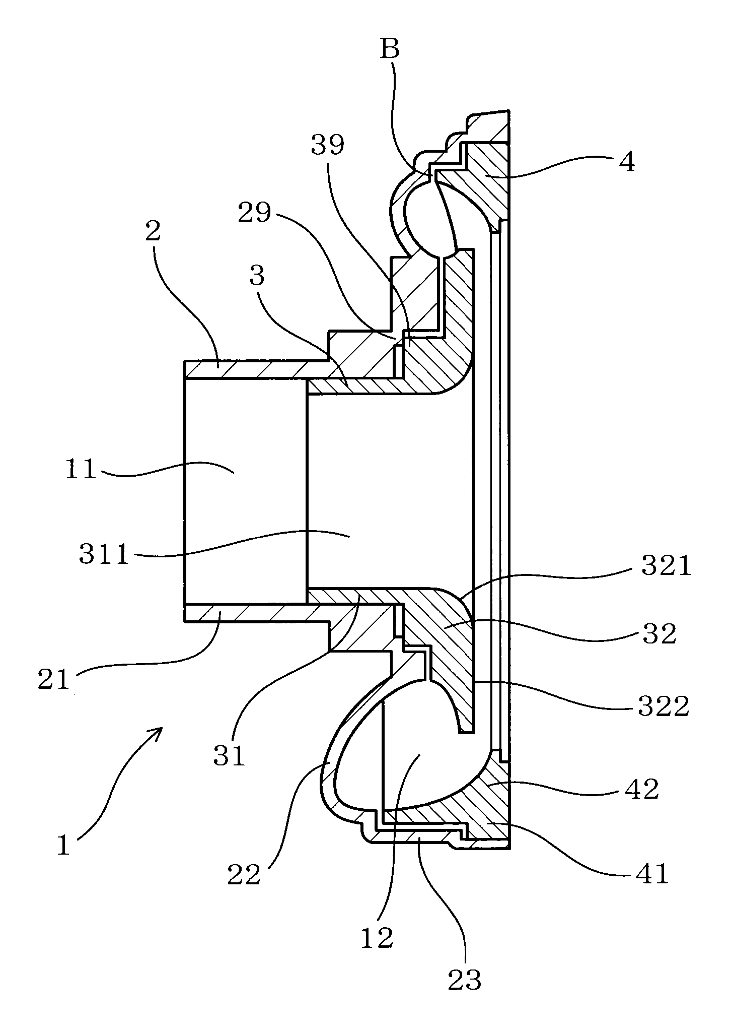
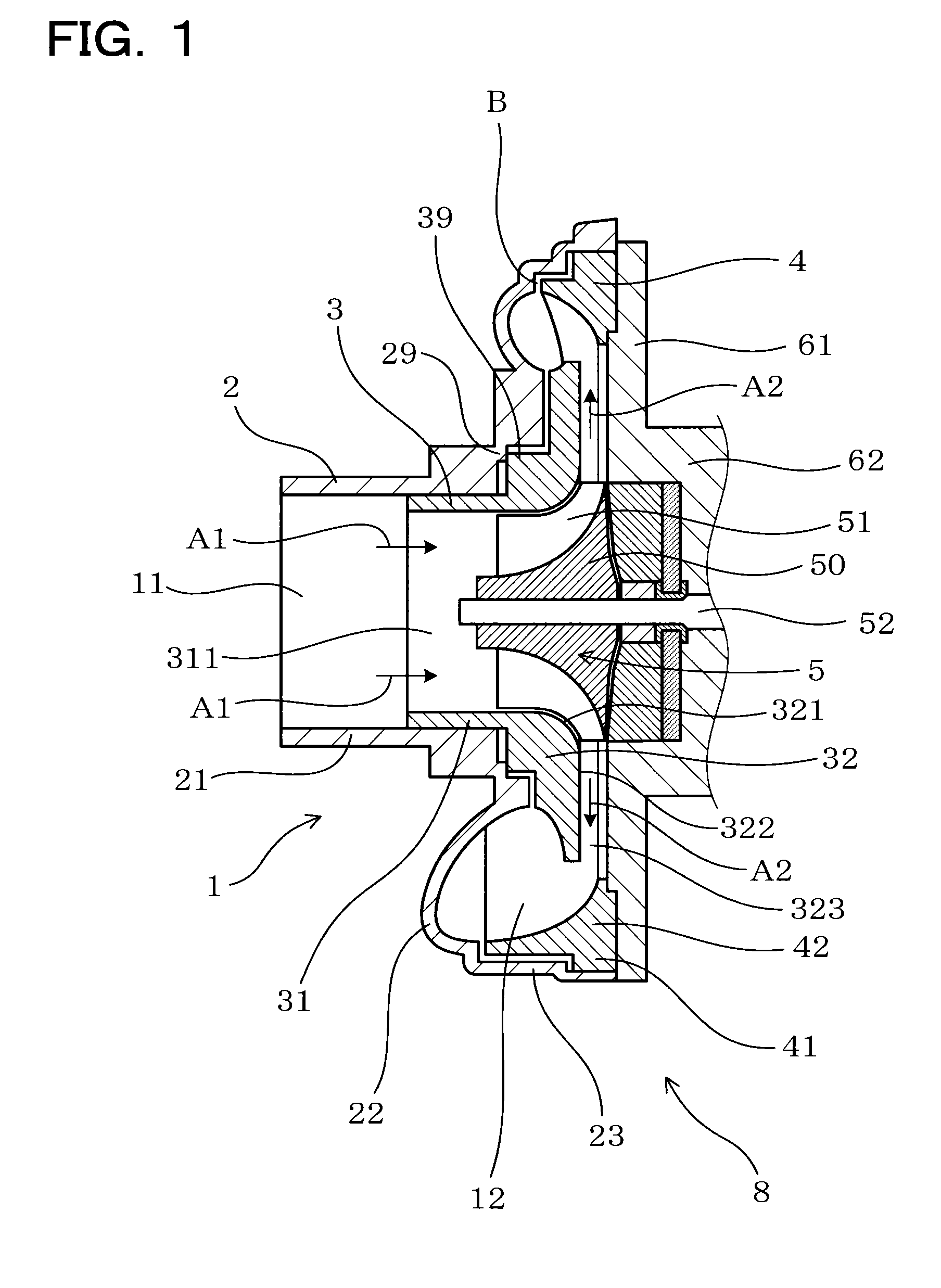
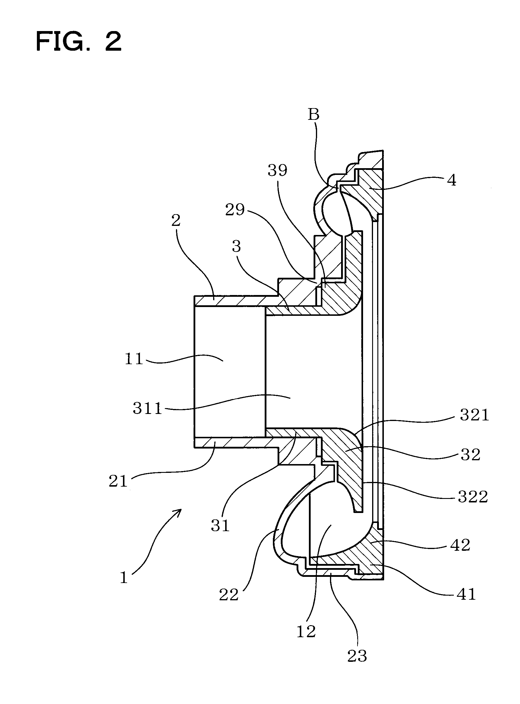
[0040]As shown in FIG. 1, a compressor housing 1 of the embodiment forms an outer shell of a compressor (compression machine) 8 used for a turbocharger (supercharger) of an automobile, is configured to house an impeller 5 that includes a plurality of blades 51, and includes an intake port 11 that takes in air A1 toward the impeller 5, and a discharge scroll chamber 12 formed along a circumferential direction on an outer circumferential side of the impeller 5 and that guides air A2 discharged from the impeller 5 to outside.

[0041]As shown in FIG. 1 and FIG. 2, the compressor housing 1 consists of three components, namely, a scroll piece 2, a shroud piece 3, and an outer circumferential annular piece 4. Specifically, the shroud piece 3 and the outer circumferential annular piece 4 are assembled in the s...


PUM

PropertyMeasurementUnit
circumferenceaaaaaaaaaa
degree of freedomaaaaaaaaaa
shapeaaaaaaaaaa

Abstract

A compressor housing is provided with a scroll piece that includes a cylindrical intake port forming section that forms an intake port, a scroll wall surface forming section that forms an air-intake side wall surface of a discharge scroll chamber, and a scroll outer circumferential section that covers an outer circumferential side of the discharge scroll chamber; a shroud piece that includes a cylindrical shroud press fitted section press fitted into the intake port forming section, and a shroud wall surface forming section that forms an inner circumferential side wall surface of the discharge scroll chamber and also forms a shroud surface that opposes an impeller and a diffuser surface; and an outer circumferential annular piece that includes an outer circumferential annular press fitted section that is press fitted inside the scroll outer circumferential section, and an outer circumferential annular wall surface forming section that forms an outer circumferential side wall surface of the discharge scroll chamber.

Description

TECHNICAL FIELD[0001]The present invention relates to a compressor housing for a supercharger configured to house an impeller including a plurality of blades, and a method of manufacturing the same.BACKGROUND ART[0002]A compressor (compression machine) used in a supercharger such as a turbocharger of an automobile includes a compressor housing configured to house an impeller that includes a plurality of blades.[0003]The compressor housing includes an intake port that takes in air toward the impeller, a discharge scroll chamber that is formed in a circumferential direction at an outer circumference of the impeller and guides air discharged from the impeller to outside, and other than the above, a portion to house the impeller, a diffuser section and the like.[0004]As a method of manufacturing a compressor housing, for example, there is a method to form the same by gravity casting. In this case, since the casting can be performed by using a so-called core, the degree of freedom for sh...

Claims


Application Information

Patent Timeline
Patent Type & Authority Applications(United States)
IPC IPC(8): F02B39/00B23P17/00
CPCB22C9/24B22D17/00F04D29/023F04D29/4206Y10T29/49243F04D29/624F05D2220/40F05D2230/21F05D2260/37F04D29/441F05D2250/52
Inventor OSUKA, RYUMATSUI, HIROKIISOGAI, TOMOYUKI
Owner OTICS CORP
Why Eureka
Try Eureka