

Method for sealing package
a sealing method and packaging technology, applied in the field of sealing methods, can solve the problems of difficult sealing of the package, difficult for the coating agent to be introduced into the inner face of the package,
- Summary
- Abstract
- Description
- Claims
- Application Information
AI Technical Summary
Benefits of technology
Problems solved by technology
Method used
Image

Examples
embodiment
1. Embodiment
1. Configuration
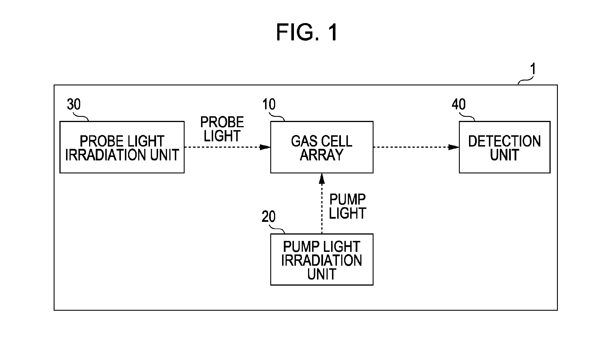
[0039]FIG. 1 is a block diagram showing a configuration of a magnetic measurement apparatus 1. The magnetic measurement apparatus 1 is a magnetic sensor that measures a magnetic field that is generated from the heart (magnetocardiography) and a magnetic field that is generated from the brain (magetoencephalography) as an index of a condition of a living body. The magnetic measurement apparatus 1 includes a gas cell array 10, a pump light irradiation unit 20, a probe light irradiation unit 30 and a detection unit 40. The gas cell array 10 has a plurality of gas cells 11. The gas cells 11 are enclosed with an alkali metal gas (for example, cesium (Cs)). The pump light irradiation unit 20 outputs a pump light (for example, light having a wavelength 894 nm corresponding to the inner diameter D1 ray of the cesium) that interacts with alkali metal atoms. A pump light has a circularly-polarized component. When the pump light is irradiated, a peripheral electron...
modified example 1
1. Modified Example 1
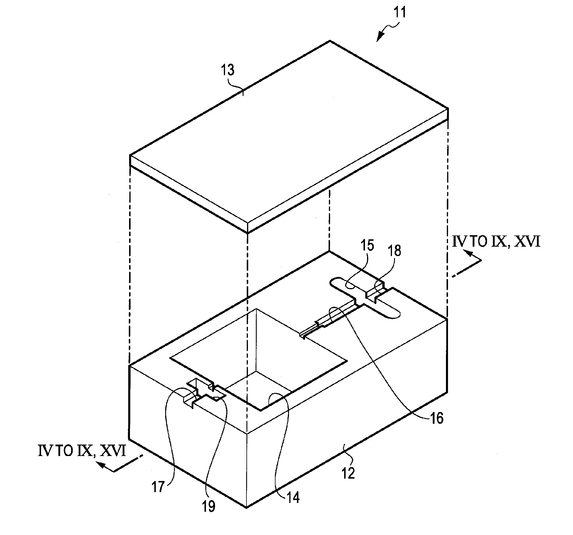
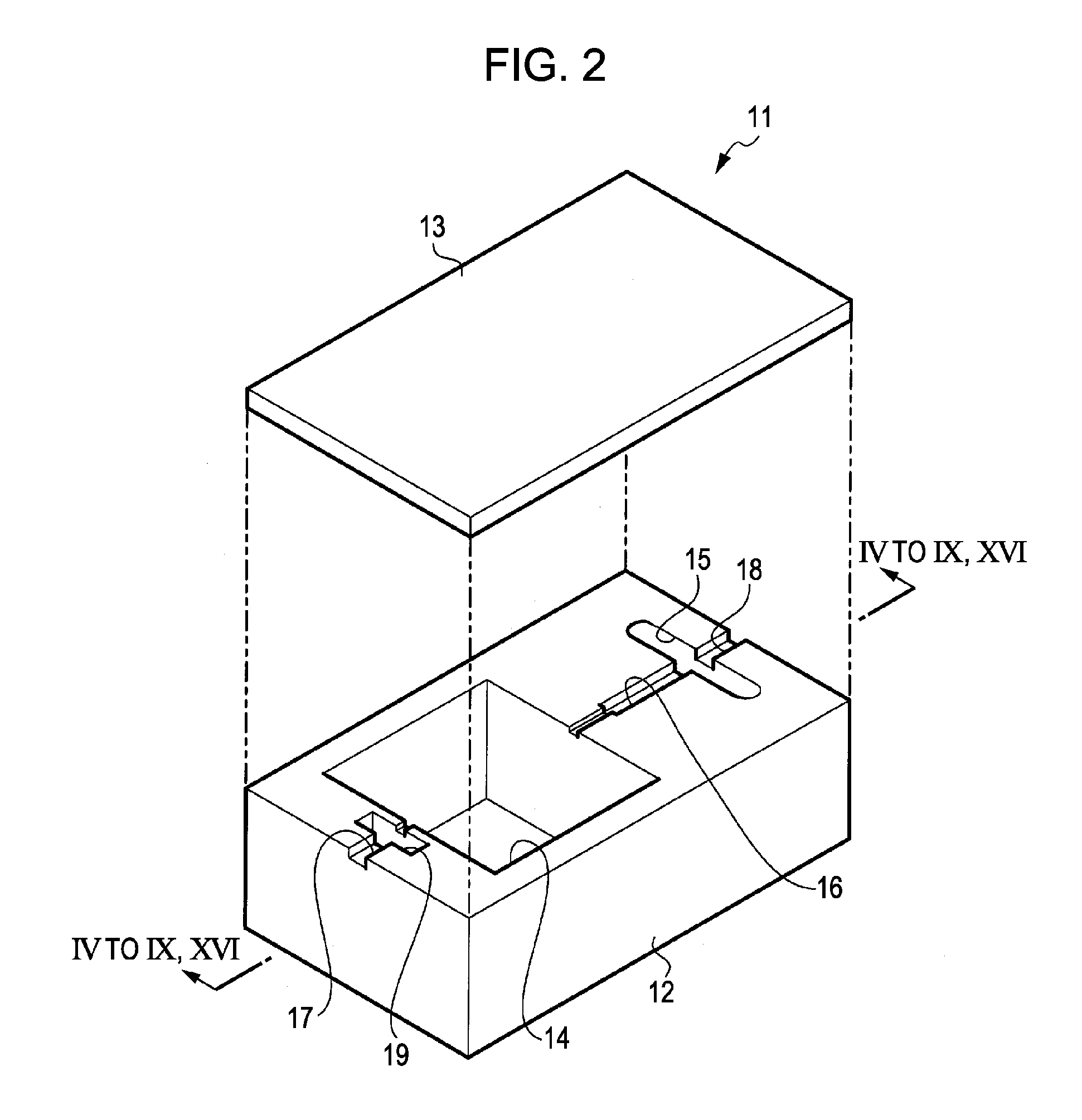
[0055]In the above-mentioned embodiment, the sealing member having the through-hole 71 was formed by the low melting point glass 60 using the metal wire 61. However, a cylindrical sealing member 81 having a pre-through-hole 73 may be used instead of the sealing member. At this time, the sealing member 81 is used as a second sealing member. A configuration of the gas cell 11 according to the modified example 1 has substantially the same configuration described in the embodiment. However, the concavity 19 is not provided in the package 12.
[0056]FIGS. 10 to 15 are views illustrating a manufacturing step of the gas cell 11 according to the modified example 1 described above. In the above-mentioned step S110 (connection step), as shown in FIG. 10, the groove 17 of the package 12 is formed with the cylindrical sealing member 81 instead of the metal wire 61. The sealing member 81 is formed by using a material such as the low melting point glass, solder and the like hav...
modified example 2
2. Modified Example 2
[0058]A gas cell array 10 is not limited to a plurality of gas cells 11 that is simply formed in parallel.
[0059]FIG. 16 is a cross-sectional view taken along XVI-XVI of the gas cell array E according to the modified example 2. The gas cell array 10E has the same configuration as the configuration in which a plurality of main chambers 14 are provided on the gas cell 11. The gas cell array 10E includes a package 12E and a lid 13E. The package 12E has four main chambers 14A to 14D. The upper of the package 12E is formed with grooves 91 to 93, in addition to concavity 15 and 19 and grooves 16 to 18 described above. The groove 91 connects a main chamber 14A to a main chamber 14B. The groove 92 connects the main chamber 14B to the main chamber 14C. The groove 93 connects the main chamber 14C to the main chamber 14D. A concavity 15 is formed adjacent to a main chamber 14D. A groove 17 is formed to be directed toward the outside from the main chamber 14A. In the gas cel...
PUM
| Property | Measurement | Unit |
|---|---|---|
| Temperature | aaaaa | aaaaa |
| Pressure | aaaaa | aaaaa |
| Melting point | aaaaa | aaaaa |
Abstract
Description
Claims
Application Information