Radiation detector and radiological image radiographing apparatus

a radiographing apparatus and detector technology, applied in the field of radiographing detectors and radiographing apparatuses, can solve the problems of not necessarily obtaining high quality, and achieve the effects of improving the sensitivity of the entire radiation detector, increasing the cost, and improving the quality of the obtained radiograph

Active Publication Date: 2013-02-28
FUJIFILM CORP
View PDF44 Cites 29 Cited by
  • Summary
  • Abstract
  • Description
  • Claims
  • Application Information

AI Technical Summary

Benefits of technology

[0040]Thus, since the radiological image radiographing apparatus according to the twenty-third aspect of the present invention includes the radiation detector of the present invention, the quality of the obtained radiological image can be improved without causing an increase in cost. In addition, according to the present invention, new image information is generated by adding, for each corresponding pixel, the image information indicated by electric charges read from the substrate and the second substrate. As a result, the sensitivity of the entire radiation detector can be improved.
[0041]According to the present invention, the effect can be obtained in which the quality of an obtained radiological image can be improved without causing an increase in cost.

Problems solved by technology

Accordingly, there has been a problem in that the high quality is not necessarily obtained.
Accordingly, similar to the technique disclosed in JP2002-181941A, there has been a problem in that the high quality is not necessarily obtained.

Method used


Image

  • Radiation detector and radiological image radiographing apparatus
  • Radiation detector and radiological image radiographing apparatus
  • Radiation detector and radiological image radiographing apparatus

Examples


first embodiment

[0071]First, the configuration of an indirect conversion-type radiation detector 20 according to the present embodiment will be described.

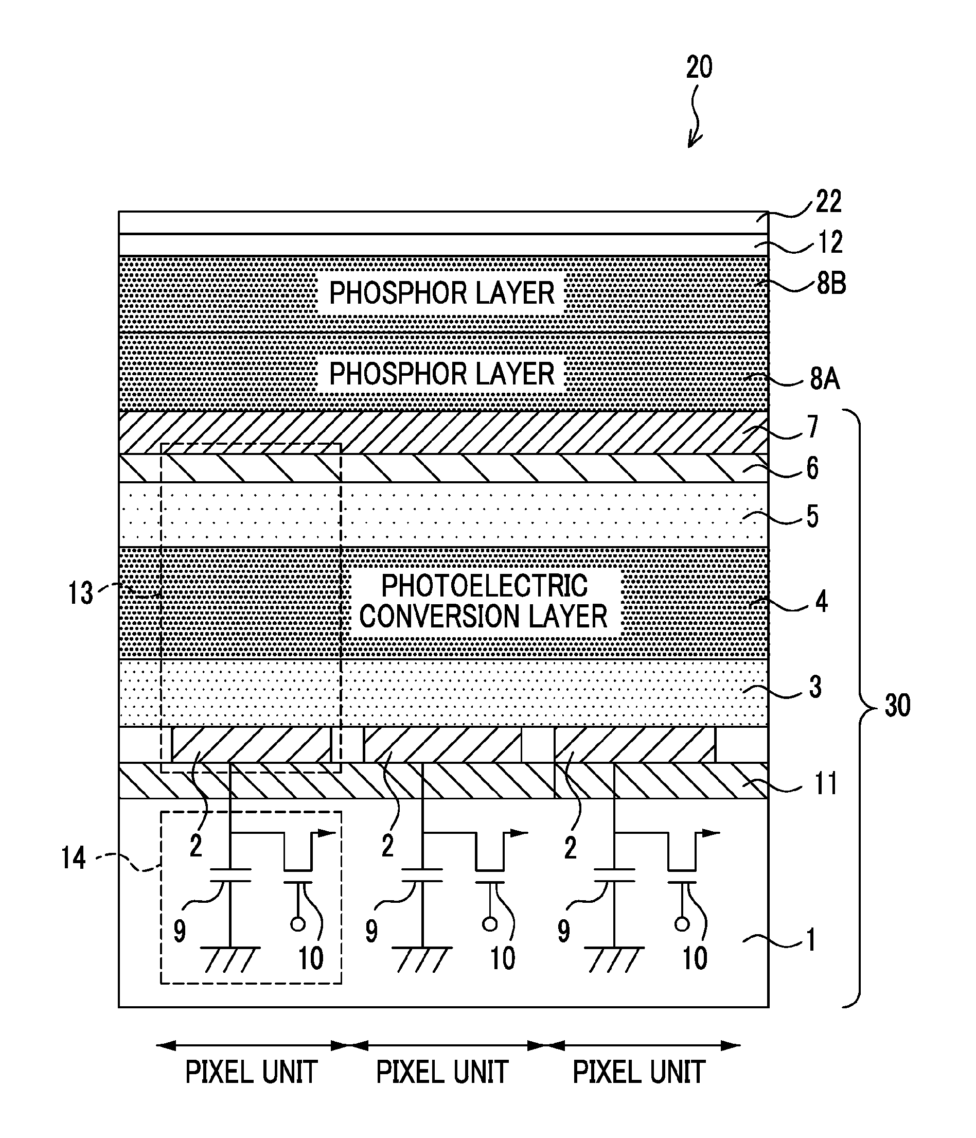
[0072]FIG. 1 is a schematic cross-sectional view showing the configuration of three pixel units of the radiation detector 20 which is an embodiment of the present invention.

[0073]In the radiation detector 20, a signal output section 14 (first switching element), a sensor section 13 (first photoelectric conversion element), a transparent insulating layer 7, a scintillator 8A (first phosphor layer), a scintillator 8B (second phosphor layer), a reflective layer 12, and a base 22 are laminated on an insulating substrate 1 in this order. A pixel unit is formed by the signal output sections 14 and the sensor sections 13. A plurality of pixel units are arrayed on the substrate 1, and each pixel unit is configured such that the signal output section 14 and the sensor section 13 overlap each other. In addition, in the present embodiment, a TFT substrate 30...

second embodiment

[0161]Next, a second embodiment will be described.

[0162]First, the configuration of an indirect conversion type radiation detector 20B according to the second embodiment will be described with reference to FIG. 10.

[0163]In the radiation detector 20B, a TFT substrate 30A obtained by forming a signal output section 14, a sensor section 13, and a transparent insulating layer 7 in this order, a scintillator 8A, a scintillator 8B, and a TFT substrate 30B with the same configuration as the TFT substrate 30A are laminated on an insulating substrate 1 in this order. A pixel unit is formed by the signal output sections 14 and the sensor sections 13 of the TFT substrates 30A and 30B. A plurality of pixel units are arrayed on the substrate 1, and each pixel unit is configured such that the signal output section 14 and the sensor section 13 overlap each other. In addition, the TFT substrate 30B is formed by forming the signal output section 14 (second switching element), the sensor section 13 (...


PUM


Abstract

A radiation detector and a radiological image radiographing apparatus capable of improving the quality of an obtained radiological image without causing an additional cost are provided. A first scintillator configured to include columnar crystals generating first light corresponding to a radiation emitted through a TFT substrate is laminated on the other surface of the TFT substrate that has a first photoelectric conversion element, which has one surface from which a radiation is emitted and the other surface from which at least one of the first light and the second light is emitted and which generates electric charges corresponding to the light, and a first switching element. A second scintillator which generates second light corresponding to a radiation emitted through the first scintillator and has different energy characteristics of absorbed radiations from the first scintillator is laminated on a surface of the first scintillator not facing the TFT substrate.

Description

BACKGROUND OF THE INVENTION[0001]1. Field of the Invention[0002]The present invention relates to a radiation detector and a radiological image radiographing apparatus. In particular, the present invention relates to a radiation detector which detects an emitted radiation and a radiological image radiographing apparatus which radiographs a radiological image expressed by the radiation detected by the radiation detector.[0003]2. Description of the Related Art[0004]In recent years, a radiation detector such as an FPD (Flat Panel Detector), which has a radiation-sensitive layer disposed on a TFT (Thin Film Transistor) active matrix substrate which can convert a radiation such as an X-ray directly into digital data, has been put to practical use. A radiological image radiographing apparatus using this radiation detector is advantageous in that an image can be immediately checked and accordingly fluoroscopy (moving image radiographing), which is for radiographing a radiological image cont...

Claims


Application Information

Patent Timeline
Patent Type & Authority Applications(United States)
IPC IPC(8): G01T1/20
CPCA61B6/4216G01T1/202A61B6/4283G01T1/2012
Inventor NISHINO, NAOYUKIIWAKIRI, NAOTONAKATSUGAWA, HARUYASUSATO, KEIICHIROOHTA, YASUNORI
Owner FUJIFILM CORP
Why Eureka
Try Eureka