
Nb3Sn SUPERCONDUCTOR WIRE AND METHOD FOR MANUFACTURING Nb3Sn SUPERCONDUCTOR WIRE

a superconductor wire and superconductor wire technology, which is applied in the direction of superconductors/hyperconductors, superconductors/coils, magnetic bodies, etc., can solve the problems of non-uniform deformation of the cross-section of the wire, wire breakage, distortion, etc., and achieve high critical current density (jc) characteristics

Inactive Publication Date: 2013-02-28
SH COPPER PROD CO LTD
View PDF2 Cites 35 Cited by
  • Summary
  • Abstract
  • Description
  • Claims
  • Application Information

AI Technical Summary

Benefits of technology

The present invention provides an Nb3Sn superconductor wire with a high critical current density (Jc) that can suppress the degradation in its superconducting characteristics with respect to compression. This results in a more stable and reliable wire for use in various applications. The method for manufacturing this wire is also provided.

Problems solved by technology

If the reinforcing members made of Ta are disposed at the center part of the multicore wire and Sn is provided at the outer periphery of the multicore wire as in the conventional device, the hardness distribution at the cross-section of the multicore wire will be large, so that a non-uniform deformation of the cross-section of the wire, breakage of the wire, and the like may be caused during the wire drawing.
Further, in the method of replacing the center filaments of the multicore wire with the reinforcing members, the strength of the entire wire can be improved by the incorporation of the reinforcing members, however, the distortion may be caused due to the absence of the reinforcing member in each Nb3Sn filament.
However, the distortion actually applied to the wire is not only the tensile strain in the longitudinal direction of the wire.
In such a case, even though the reinforcing member is disposed at the center part of the multicore wire, the distortion will be applied to the respective filaments, so that the degradation in wire characteristics will be caused.
On the contrary, since the spacing between the filaments is limited to prevent the filaments from the mutual coupling, the quantity of the composite Nb filaments was limited and the critical current characteristic was also limited.

Method used


Image

  • Nb3Sn SUPERCONDUCTOR WIRE AND METHOD FOR MANUFACTURING Nb3Sn SUPERCONDUCTOR WIRE
  • Nb3Sn SUPERCONDUCTOR WIRE AND METHOD FOR MANUFACTURING Nb3Sn SUPERCONDUCTOR WIRE
  • Nb3Sn SUPERCONDUCTOR WIRE AND METHOD FOR MANUFACTURING Nb3Sn SUPERCONDUCTOR WIRE

Examples


example 1

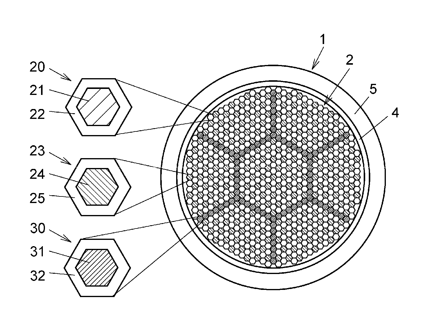
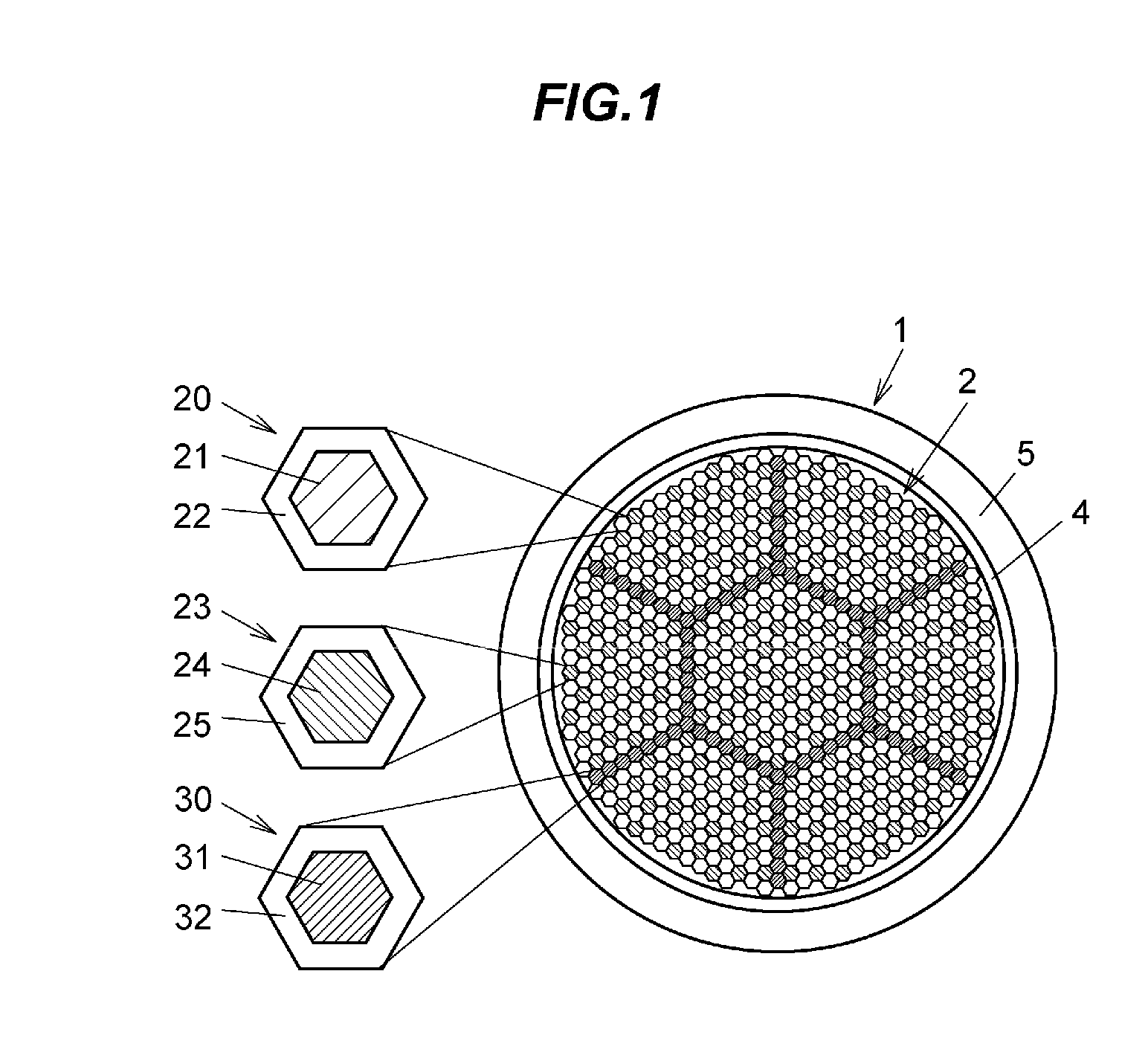
[0080]Firstly, a method for manufacturing the precursor 1 for the Nb3Sn superconductor wire in Example 1 will be explained below.

[0081]At first, Nb-1 wt % Ta alloy rod (Nb core 21) having an outer diameter of 20 mm was inserted into a Cu pipe having an outer diameter of 24 mm and an inner diameter of 20.2 mm to provide a composite material. This composite material was area-reduced by die drawing in which this composite material is put through a die having an opening having a hexagonal cross-section to provide the Nb filament 20 having a hexagonal cross-section in which a distance between opposite sides is 1 mm.

[0082]Next, Sn-alloy material containing 2 wt % of Ti (Sn-2 wt % Ti) (Sn core 24) having an outer diameter of 20 mm was inserted into a Cu pipe having an outer diameter of 23 mm and an inner diameter of 20.2 mm to provide a composite material. This composite material was area-reduced by die drawing in which this composite material is put through a die having an opening having ...

examples 2 and 3

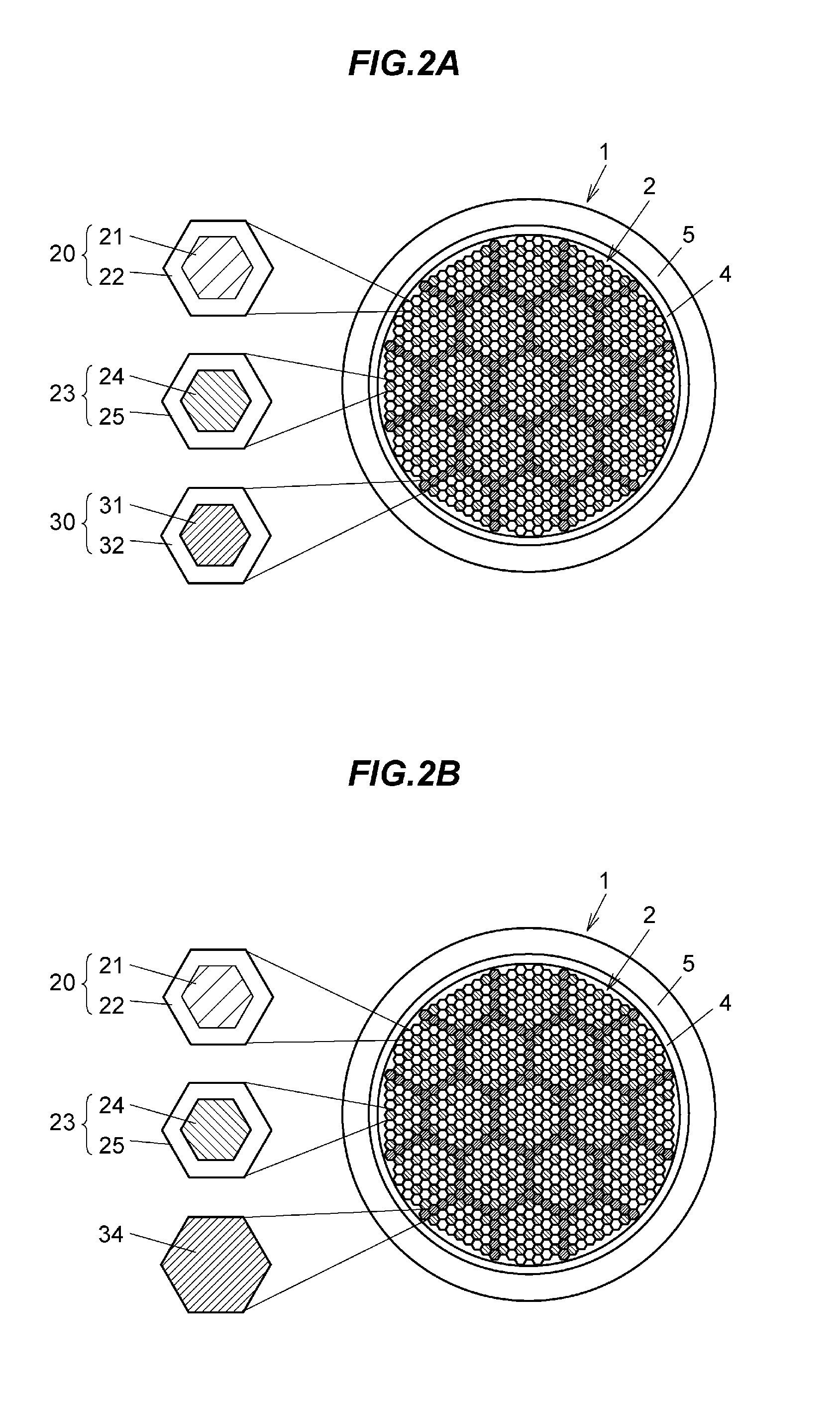
[0088]FIG. 2A is a lateral cross-sectional view showing a cross-sectional structure of a precursor for an Nb3Sn superconductor wire in each of Examples 2, 4 and 5. FIG. 3 is a lateral cross-sectional view showing a cross-sectional structure of a precursor for an Nb3Sn superconductor wire in Example 3.

[0089]The precursor 1 for the Nb3Sn superconductor wire in each of Examples 2 and 3 was manufactured by the method similar to that in Example 1, except the number of divided parts of the filament assembly 2 with the Ta filaments 30 was varied.

[0090]In Example 2, as shown in FIG. 2A, the filament assembly 2 comprising 396 pieces of Nb filaments 20 and 211 pieces of the Sn filaments 23 was divided into nineteen (19) parts by 162 pieces of the Ta filaments 30 such that the Sn filaments 23 are not adjacent to each other, to provide a multicore billet. The multicore billet was area-reduced, to provide a precursor 1 for an Nb3Sn superconductor wire having a wire diameter of 1 mm.

[0091]In Exam...

examples 4 , 5

Examples 4, 5, and 6

[0093]The precursor 1 for the Nb3Sn superconductor wire in each of Examples 4 and 5 was manufactured by the method similar to that in Example 2, except a cross-sectional area ratio of the Cu coating layer 32 of the Ta filament 30 as the reinforcing member was varied.

[0094]In Example 4, as shown in FIG. 2A, Ta rod (Ta core 31) having an outer diameter of 20 mm was inserted into a Cu pipe having an outer diameter of 28 mm and an inner diameter of 20.2 mm to provide a composite material (Cu ratio is 0.67). This composite material was area-reduced to provide the Ta filament 30 having a hexagonal cross-section in which a distance between opposite sides is 1 mm as the reinforcing member. Herein, the Cu ratio is a ratio of a lateral cross-sectional area of the Cu part wherein a total lateral cross-sectional area of all filaments is 1.

[0095]In Example 5, as shown in FIG. 2A, a Cu pipe having an outer diameter of 22 mm and an inner diameter of 20.2 mm was prepared. Ta rod...


PUM

PropertyMeasurementUnit
Fractionaaaaaaaaaa
Fractionaaaaaaaaaa
Superconductivityaaaaaaaaaa

Abstract

An Nb3Sn superconductor wire is manufactured by heating a precursor for an Nb3Sn superconductor wire. The precursor includes a Cu tube made of Cu or Cu-alloy, assemblies, each of which includes Nb filaments disposed in the Cu tube, and each of the Nb filaments includes an Nb core made of Nb or Nb-alloy. Each of the assemblies also includes Sn filaments disposed in the Cu tube, and each of the Sn filaments includes a Sn core made of Sn or Sn-alloy. The precursor also includes reinforcing filaments disposed in the Cu tube for dividing the assemblies such that the assemblies are not adjacent to each other. By heating the precursor, Sn in the Sn core is diffused into the Nb core to produce Nb3Sn.

Description

[0001]The present application is based on Japanese Patent Application No. 2011-184097 filed on Aug. 25, 2011 and Japanese Patent Application No. 2012-181532 filed on Aug. 20, 2012, the entire contents of which are incorporated herein by reference.BACKGROUND OF THE INVENTION[0002]1. Field of the Invention[0003]The present invention relates to an Nb3Sn superconductor wire having high critical current density (Jc) characteristic and high strength to be applicable for a high-field magnet, and a method for manufacturing an Nb3Sn superconductor wire.[0004]2. Related Art[0005]As a method for manufacturing an Nb3Sn superconductor wire, the bronze method has been used widely. The bronze method is a method including steps of forming a wire with a configuration in which a lot of Nb filaments are disposed within Cu—Sn based alloy matrix, i.e. so-called bronze matrix, diffusing Sn of the Cu—Sn based alloy into the Nb filaments by heat treatment to produce Nb3Sn in some portions of the Nb filamen...

Claims


Application Information

Patent Timeline
IPC IPC(8): H01B12/10H01L39/24
CPCY10T29/49014H01L39/2409H10N60/0184
Inventor OHATA, KATSUMIWADAYAMA, YOSHIHIDENAKAGAWA, KAZUHIKOKIMURA, MORIO
Owner SH COPPER PROD CO LTD
Learn More