Endoscopic diagnosis system

a diagnosis system and endoscope technology, applied in the field of endoscope diagnosis system, can solve the problems of inability to use fluorescence emitted from an autofluorescent substance in sufficient amounts, and inability to know whether it is an inflamed region or a large quantity of blood. , to achieve the effect of reducing the effect of light absorption, increasing and decreasing the amount, and increasing the amount o

Inactive Publication Date: 2013-02-28
FUJIFILM CORP
View PDF5 Cites 10 Cited by
  • Summary
  • Abstract
  • Description
  • Claims
  • Application Information

AI Technical Summary

Benefits of technology

[0024]The present invention enables acquisition of an autofluorescence image free from the effects of light absorption by blood by correcting the autofluorescence image based on a reflected light image. For example, an autofluorescence image free from the effects of light absorption by blood may be obtained by correcting the intensities of the autofluorescence image signals using a correction coefficient corresponding to the reflectance of a reflected light image having the same wavelength band as the emission wavelength band of the autofluorescence.
[0025]Further, obtaining an attenuation ratio of excitation light and autofluorescence ba...

Problems solved by technology

However, the method of JP 2009-95683 A is incapable of distinguishing an inflamed region from a region containing a large quantity of blood such as a thick blood vessel, which is not an inflamed region, and therefore one cannot know whether it is an inflamed region or a large quantity of blood that is under observation.
The method of JP 2009-95683 A had a problem that the fluorescence intensity must be increased with a fluorescence probe to avoid the weakening of...

Method used


Image

  • Endoscopic diagnosis system
  • Endoscopic diagnosis system
  • Endoscopic diagnosis system

Examples


first embodiment

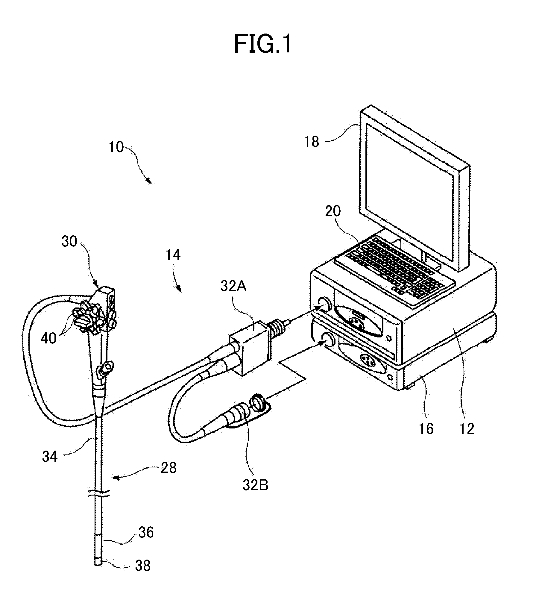
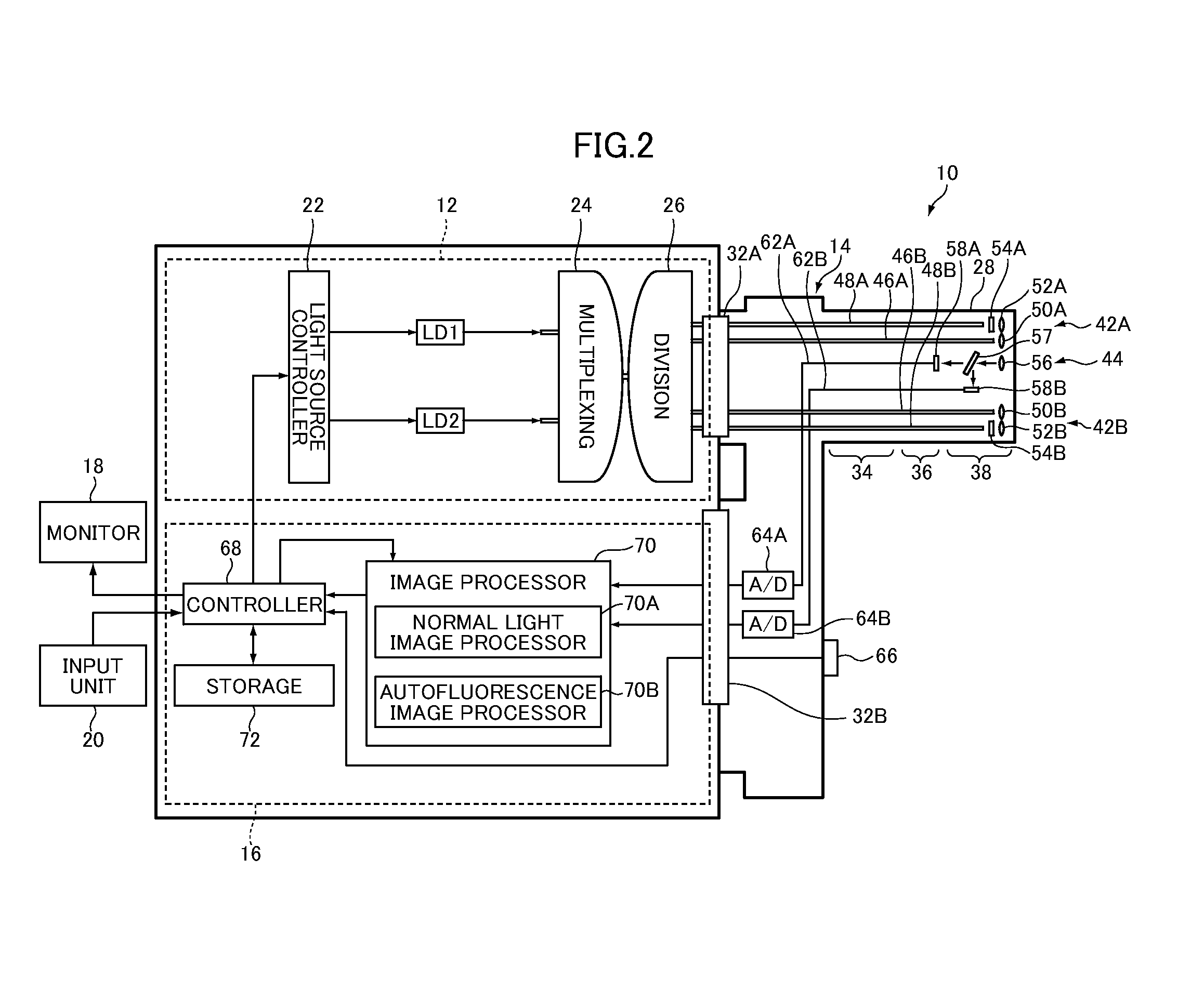
[0136]FIG. 19 is an external view of an embodiment illustrating a configuration of an endoscopic diagnosis system according to the second aspect of the invention; FIG. 20 is a block diagram of a first embodiment illustrating an internal configuration of the system shown in FIG. 19. An endoscopic diagnosis system 10A illustrated in that drawing has the same configuration as the endoscopic diagnosis system 10 according to the first aspect shown in FIGS. 1 and 2 except that the light source device 12 and the endoscope device 14 are respectively replaced with a light source device 12A and an endoscope device 14A. In the description to follow, like components are given like reference characteristics and are not described in detail in the following description, and focus is placed on different components.

[0137]Likewise, the endoscopic diagnosis system 10A is capable of normal light observation mode and autofluorescence observation mode.

[0138]According to this embodiment, the laser light s...

second embodiment

[0177]FIG. 23 is a block diagram of the second embodiment illustrating an internal configuration of the endoscopic diagnosis system according to the second aspect shown in FIG. 19. An endoscopic diagnosis system 10B shown in that figure differs from the endoscopic diagnosis system 10A shown in FIG. 20 only in part of the configuration of the light source device, 12B, and the endoscope device, 14B, and like components other than these components are assigned like reference characteristics. No detailed description is made of the shared components below. The description to follow is focused on the differences between the two systems.

[0178]As compared with the light source device 12A of the endoscopic diagnosis system 10A shown in FIG. 20, the light source device 12B additionally comprises a laser light source LD3. The laser light source LD3 emits monochromatic light (narrowband light) having a central wavelength of 630 nm and a given wavelength range. The laser light source LD3 emits m...


PUM


Abstract

An endoscopic diagnosis system includes a light source unit for emitting green and red light, blue and green light, or white light and excitation light having different central wavelengths for causing an autofluorescent substance to emit autofluorescence, an imaging unit for receiving reflected light from the observation region to acquire a reflected light image when the observation region is illuminated with the illumination light emitted, and receiving autofluorescence that is emitted from the autofluorescent substance, absorbed by blood, and decreases according to the amount of the blood to acquire an autofluorescence image when the observation region is irradiated with the excitation light emitted, and an image correction unit for correcting the autofluorescence image based on the reflected light image.

Description

BACKGROUND OF THE INVENTION[0001]The present invention relates to an endoscopic diagnosis system for acquiring an autofluorescence image by imaging autofluorescence emitted from an autofluorescent substance contained in a subject's observation region (organism).[0002]There is conventionally used an endoscope device in which normal light (white light) emitted from a light source device is guided to the tip of an endoscope to illuminate an observation region of a subject, and the reflected light is imaged to acquire a normal light image (white light image) for normal light observation (white light observation). In recent years, there is used an endoscope device in which a region of a subject under observation is irradiated with excitation light (special light) used for observation of autofluorescence, and autofluorescence emitted from an autofluorescent substance is imaged to acquire an autofluorescence image (special light image) for autofluorescence observation (special light observ...

Claims


Application Information

Patent Timeline
IPC IPC(8): A61B1/06A61B6/00
CPCA61B1/0638A61B1/00006A61B1/00009A61B1/0653A61B1/05A61B1/063A61B1/043A61B1/000095A61B1/0655
Inventor YAMAMOTO, HIROAKISAITO, TAKAAKIYAMAGUCHI, HIROSHI
Owner FUJIFILM CORP
Why Eureka
Try Eureka