Fault detection system for a generator

a technology of fault detection system and generator, which is applied in the direction of power supply testing, process and machine control, instruments, etc., can solve the problems of power converter not being activated, power converters not being able to operate, and faults between cables that connect generators

Inactive Publication Date: 2013-02-28
GENERAL ELECTRIC CO
View PDF5 Cites 28 Cited by
  • Summary
  • Abstract
  • Description
  • Claims
  • Application Information

AI Technical Summary

Problems solved by technology

However, a fault may occur on the output of the permanent magnet generator while voltage is being produced.
For example, the power converter may not be activated if there is not adequate wind, maintenance work is being performed on the wind turbine, or in the event the wind turbine is nonoperational.
A fault may occur between the cables that conne

Method used


Image

  • Fault detection system for a generator
  • Fault detection system for a generator
  • Fault detection system for a generator

Examples


Embodiment Construction

[0016]As used herein the terms module and sub-module refer to an application specific integrated circuit (ASIC), an electronic circuit, a processor (shared, dedicated, or group) and memory that executes one or more software or firmware programs, a combinational logic circuit, and / or other suitable components that provide the described functionality.

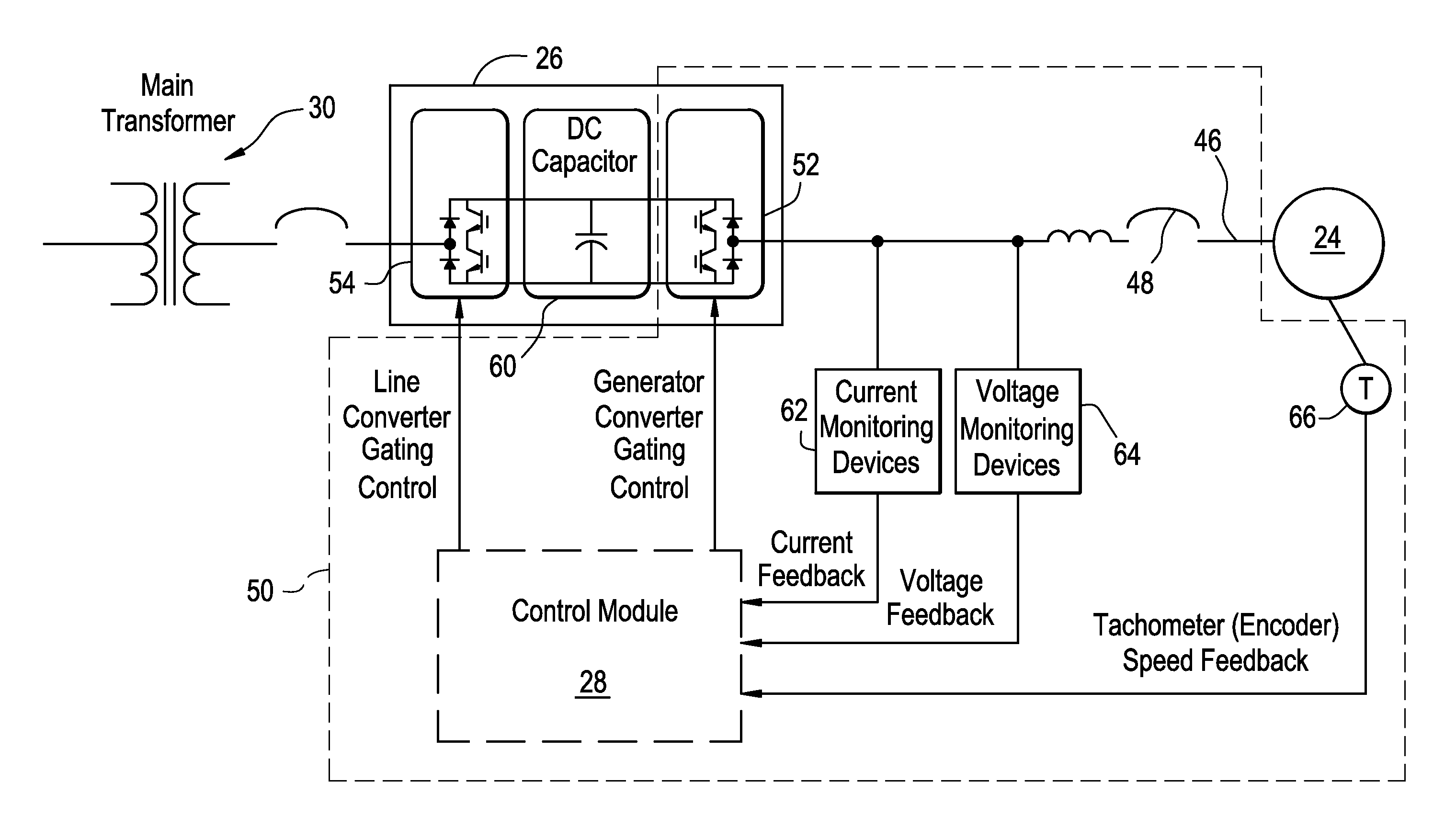
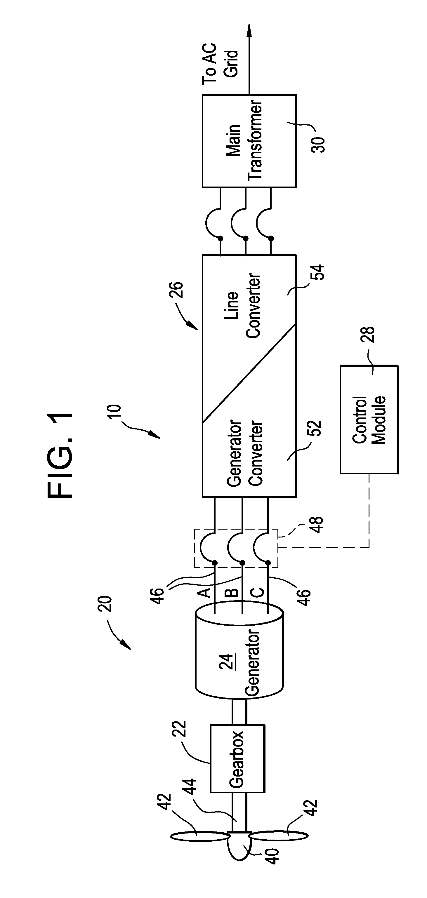
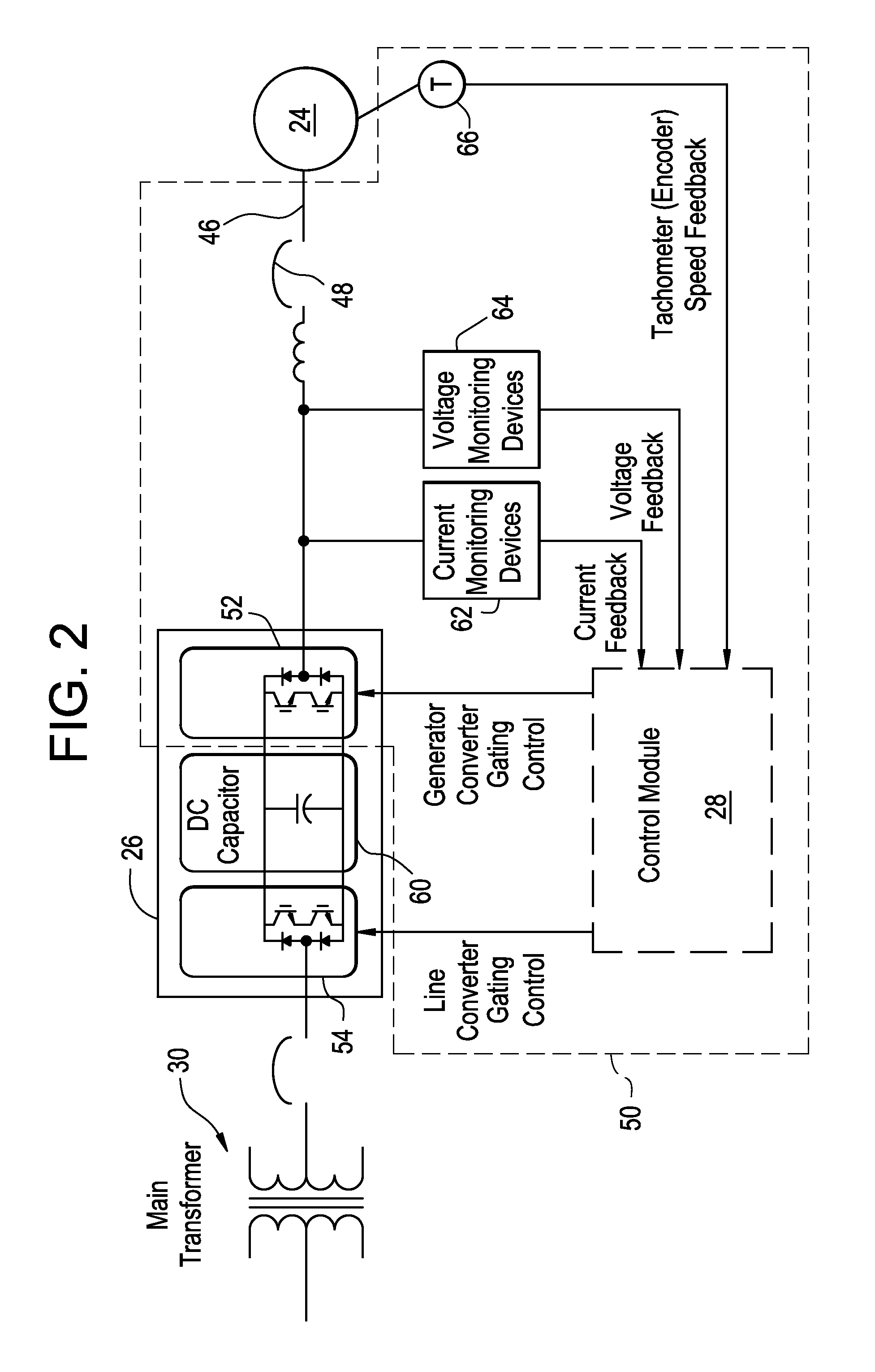
[0017]Referring now to FIG. 1, a schematic exemplary wind power plant 10 is illustrated. The wind power plant 10 includes a wind turbine 20, a gearbox 22, a generator 24, a main power convertor 26, a converter controller 28, and a main transformer 30. The wind turbine 20 includes a hub 40 and a plurality of rotor blades 42 that are connected to the hub 40. A shaft 44 transfers energy from the wind turbine 20 to the generator 24 through the gearbox 22. The rotational speed of the shaft 44 is dependent on wind speed. The generator 24 is typically any type of machine that converts the mechanical energy from the shaft 44 into electrical energ...


PUM


Abstract

A fault detection system is provided, and includes a generator, a power converter, a breaker, a current monitoring device, and a control module. The power converter is selectively connected to the generator and is selectively activated to produce a test voltage. The breaker is located between the generator and the power converter for selectively connecting the generator to the power converter. The breaker includes an open position and a closed position. The current monitoring device is located between the generator and the power converter. The current monitoring device measures a line current between the generator and the power converter. The control module is in communication with the current monitoring device and the power converter. The control module has a memory with a threshold current value.

Description

BACKGROUND OF THE INVENTION[0001]The subject matter disclosed herein relates to a fault detection system system, and more specifically to a fault detection system including a generator and a power converter that is selectively connected to the generator.[0002]Wind turbines are one alternative to conventional sources of energy. A wind turbine includes multiple blades that are connected to a rotor, where spinning of the blades by wind spins a shaft of the rotor. The rotor is connected to a generator that generates electricity. Some wind turbines include a gearbox that couples the rotor to the generator. Various types of generators are employed in wind turbines such as, for example, induction machines and separately excited synchronous machines. Specifically, one type of generator that may be employed is a permanent magnet generator. The permanent magnet generator allows for higher efficiency but, because the permanent magnet generator is excited by permanent magnets, the permanent mag...

Claims


Application Information

Patent Timeline
IPC IPC(8): G06F1/28
CPCG01R31/42G01R31/343F05B2270/337F05B2260/80F05B2270/327F05B2220/7068
Inventor KLODOWSKI, ANTHONY MICHAELBARKER, SIDNEY ALLEN
Owner GENERAL ELECTRIC CO
Why Eureka
Try Eureka