Aircraft tail surface with a leading edge section of undulated shape

a technology of leading edge section and aircraft tail surface, which is applied in the direction of aircraft stabilisation, wing shape, drag reduction, etc., can solve the problems of increasing the angle of attack, wing liable to stall, and delay of stall at high angles of attack, so as to improve the aerodynamic performance

Active Publication Date: 2013-03-07
AIRBUS OPERATIONS SL
View PDF4 Cites 14 Cited by
  • Summary
  • Abstract
  • Description
  • Claims
  • Application Information

AI Technical Summary

Benefits of technology

[0014]It is an object of the present invention to provide an aircraft tail surface with an improved aerodynamic performance in icing conditions.
[0015]It is another object of the present invention to provide an aircraft tail surface that reduces the detrimental effects of ice accretion in icing conditions.
[0016]These and another objects are met by an aircraft tail surface comprising a leading edge having in at least a section along the tail span an undulated shape formed by a continuous series of smooth protrusions and recesses so that, in icing conditions, the ice accretion is produced only on the peaks of said protrusions and on the bottoms of said recesses, thereby creating a channeled airflow and an arrangement of air vortices which impart energy to the airflow in the aerofoil boundary layer which delay the airflow separation that causes the stall, thus reducing the detrimental effects of ice accretion in its aerodynamic performance.
[0017]In embodiments of the present invention said leading edge section having an undulated shape is comprised between the 60%-100% of the tail span. Therefore the means for improving the aerodynamic performance of the tail surface is placed in the tail surface region of stall onset.

Problems solved by technology

The performance of aircraft tail surfaces, particularly the horizontal tail plane and the vertical tail plane, is one of the more important issues in global aircraft design because said surfaces are used as control surfaces that must provide stabilizing forces even at high angles of attack to restore the aircraft attitude.
One of the effects of said modification is the delay of stall at high angles of attack.
During flight at low speed, where the wing high lift systems are deployed, the wing is liable to stall if the pilot inadvertently flies below the stall speed or performs an unusual maneuver which increases the angle of attack beyond the stall angle of the wing.
There are several accidents documented where the root cause has been the stall of the tail in icing conditions and therefore the loss of control of the aircraft.
These methods not only are costly to install and maintain but carry the risk of not being operative when required, without prior indication.

Method used


Image

  • Aircraft tail surface with a leading edge section of undulated shape
  • Aircraft tail surface with a leading edge section of undulated shape
  • Aircraft tail surface with a leading edge section of undulated shape

Examples


Embodiment Construction

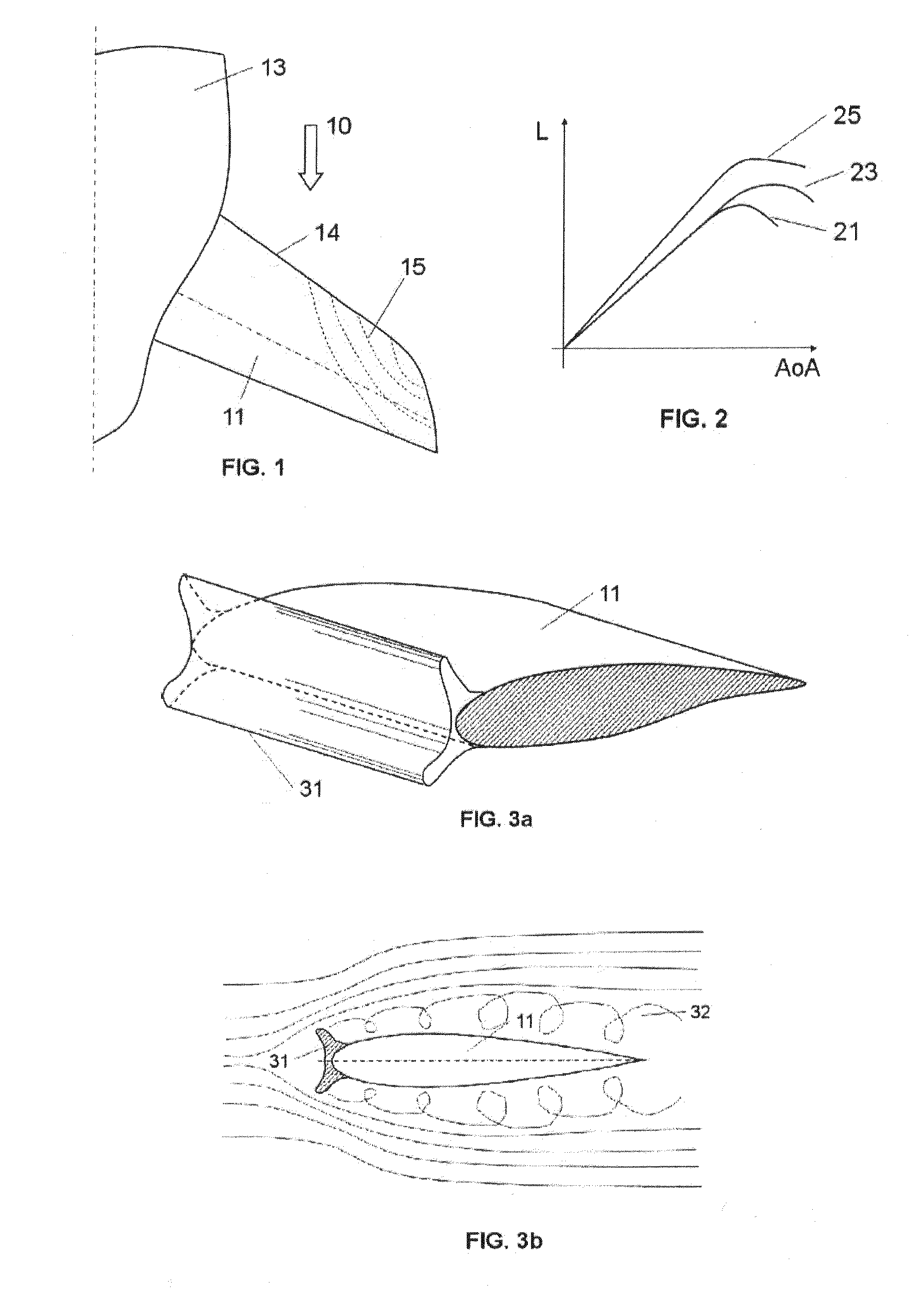
[0030]FIG. 1 shows a conventional aircraft horizontal tail plane 11 with a straight leading edge 14 attached to the aircraft fuselage 13 and the region 15 of stall onset. Arrow 10 indicates the flow direction.

[0031]FIG. 2 shows Lift vs. Angle of attack curves 21, 23, 25 for the horizontal tail plane of FIG. 1 in, respectively, a situation with icing on the leading edge of a tail plane without any special device to delay stall in icing conditions, a situation with icing on the leading edge with undulations as per the present invention, and a situation without icing. These curves show clearly that reducing the detrimental effect of ice accretion is a primary driver for delaying stall.

[0032]The loss of maximum lift capability and reduced stall angle with ice accretion is due to, as shown in FIGS. 3a and 3b, the flow separation 32 caused by the ice accretion 31 on the leading edge of the horizontal tail plane 11.

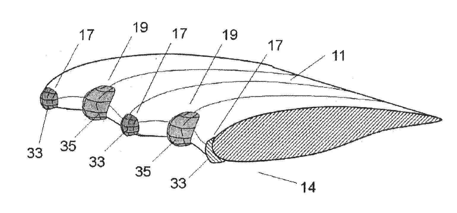
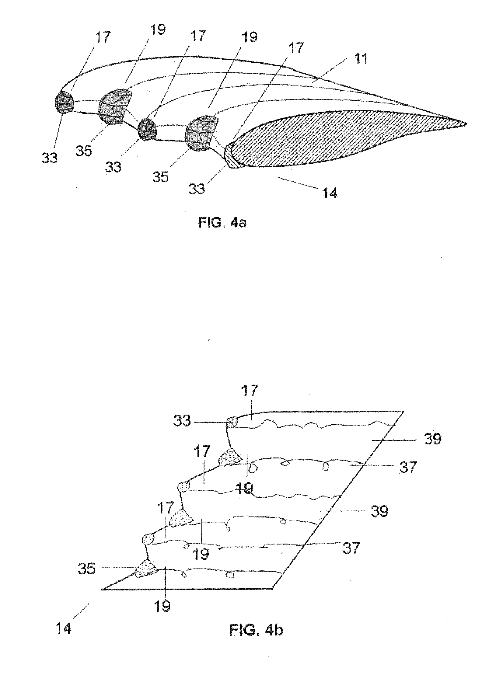
[0033]FIGS. 4a and 4b illustrates the basic idea of the present invention. ...


PUM


Abstract

An aircraft tail surface (11), such as a horizontal tail plane or a vertical tail plane, comprising a leading edge (14) having in at least a section along the tail span an undulated shape formed by a continuous series of smooth protrusions (17) and recesses (19) so that, in icing conditions, the ice accretion is produced only on the peaks (18) of said protrusions (17) and on the bottoms (20) of said recesses (19), thereby creating a channeled airflow and an arrangement of air vortices which impart energy to the airflow in the aerofoil boundary layer which delay the airflow separation that causes the stall, thus reducing the detrimental effects of ice accretion in its aerodynamic performance.

Description

FIELD OF THE INVENTION[0001]The present invention refers to aircraft tail surfaces and more in particular to a configuration of an aircraft tail surface for improving its aerodynamic performance in icing conditions.BACKGROUND OF THE INVENTION[0002]The performance of aircraft tail surfaces, particularly the horizontal tail plane and the vertical tail plane, is one of the more important issues in global aircraft design because said surfaces are used as control surfaces that must provide stabilizing forces even at high angles of attack to restore the aircraft attitude.[0003]Tail stall angle is a design constraint related to the safety of the aircraft flight and is determined by the taper and aspect ratio of the surface as well as, among other design features, the aerofoil thickness and leading edge shape, so that the aircraft industry is constantly demanding new designs of tail surfaces that allow delaying stall, particularly in icing conditions.[0004]Regarding wings, U.S. Pat. No. 6,4...

Claims


Application Information

Patent Timeline
Patent Type & Authority Applications(United States)
IPC IPC(8): B64D15/00
CPCY02T50/12B64C3/14B64C5/02B64C2003/146Y02T50/10
Inventor LLAMAS SANDIN, RAUL CARLOS
Owner AIRBUS OPERATIONS SL
Why Eureka
Try Eureka