Energy efficient climate control system for an offshore wind turbine

Active Publication Date: 2013-03-07
ADWEN OFFSHORE SL
View PDF3 Cites 39 Cited by
  • Summary
  • Abstract
  • Description
  • Claims
  • Application Information

AI Technical Summary

Benefits of technology

The present invention is a climate control system for offshore wind turbines that integrates with the component cooling system. It is an open airflow system that uses waste heat from the cooling system to warm and reduce the humidity of the air entering the nacelle. This helps meet the humidity requirements of the air inside the nacelle and reduces the size of the cooling system's radiators, which can minimize equipment corrosion and reduce the size of the radiators. The system is energy-efficient and reduces corrosion. The invention also includes a method to warm and reduce humidity in the air entering the nacelle by using waste heat from the cooling system.

Problems solved by technology

This can pose a major problem for an offshore wind turbine cooled with an open airflow system because the equipment corrosion rate increases exponentially with an increase in the relative humidity of air inside the turbine.

Method used


Image

  • Energy efficient climate control system for an offshore wind turbine
  • Energy efficient climate control system for an offshore wind turbine
  • Energy efficient climate control system for an offshore wind turbine

Examples


first embodiment

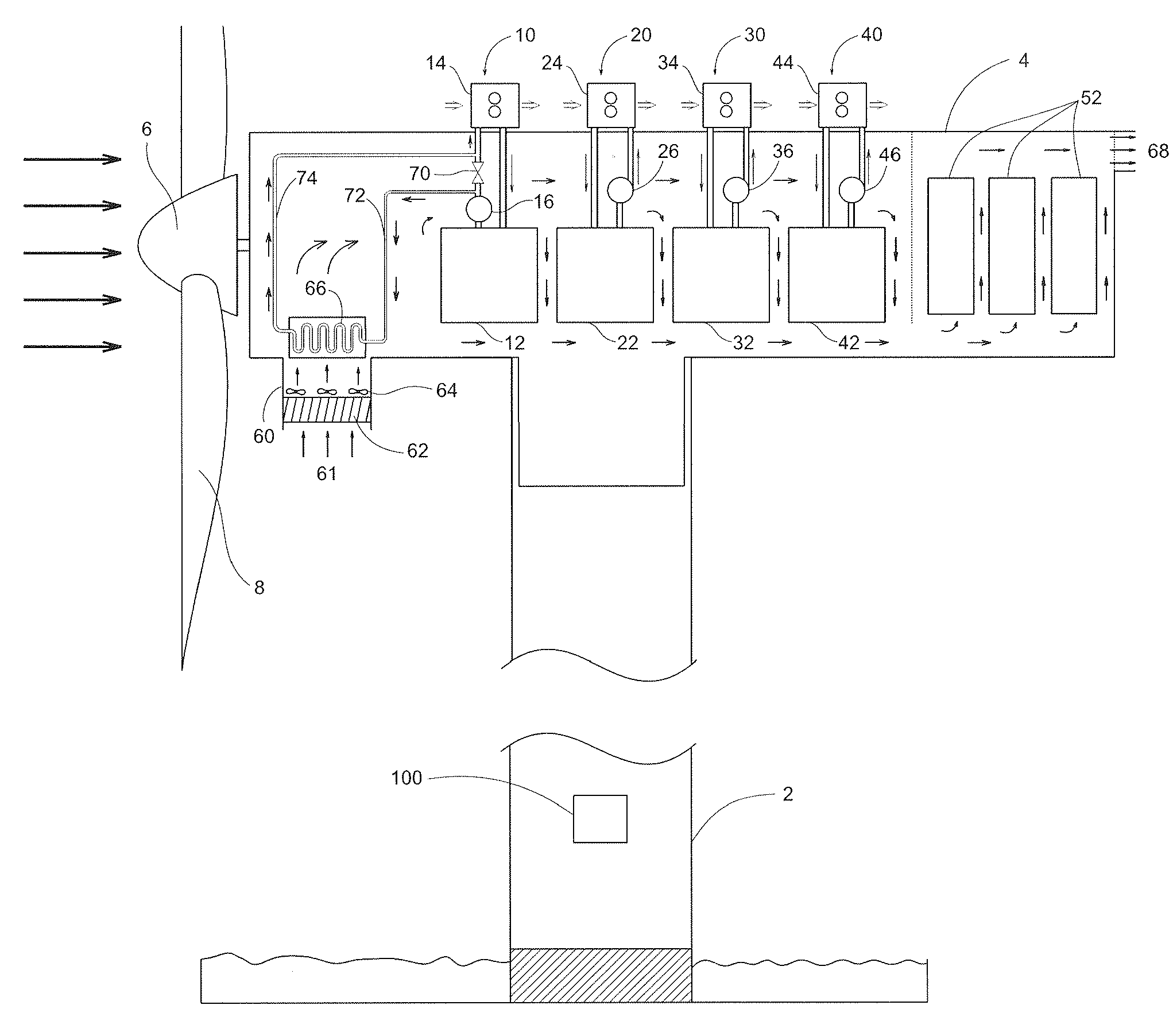
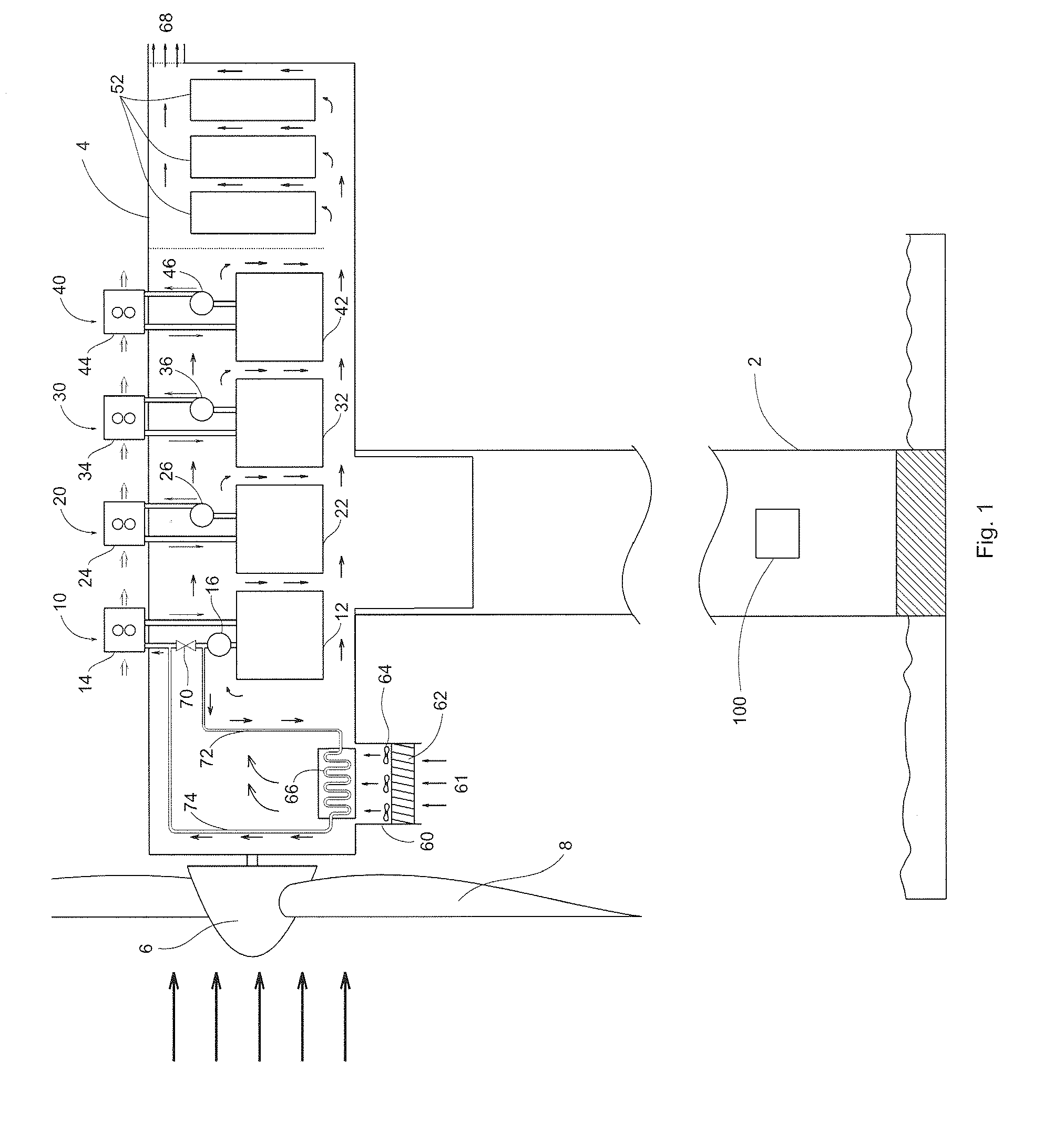
[0028]FIG. 1 shows a schematic of the climate control system of an offshore wind turbine along with the cooling system according to the present invention. The offshore wind turbine consists of a tower 2, a nacelle 4, and a rotor 6 with blades 8. In the configuration shown in FIG. 1, the cooling system comprises cooling circuits 10, 20, 30, and 40 that carry the heat generated by the drivetrain 12, the generator 22, the hydraulic system 32, and the converter 42, respectively, to outside the nacelle, and dissipate the heat to the ambient air through air cooled radiators 14, 24, 34, and 44, respectively. Pumps 16, 26, 36, and 46 circulate the coolant in the cooling circuits 10, 20, 30, and 40, respectively.

[0029]The climate control system has an air handling unit 60 at the nacelle front bottom that helps supply clean ambient air to the nacelle 4 at a relative humidity that can be well below 70%. This is accomplished by the components of the air handling unit 60, namely, the air inlet 6...

second embodiment

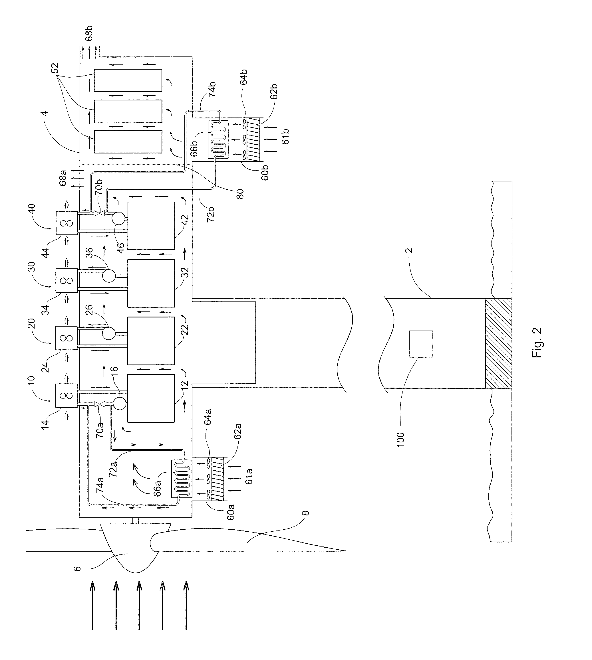
[0033]FIG. 2 shows a schematic of the climate control system according to the present invention, having two airflow systems through the nacelle 4. In this case, a wall 80 between the converter 42 and the transformer 52 separates the nacelle 4 into two sections. The first airflow system comprises an air handling unit 60a with its components, namely, the air inlet 61a, the filter 62a, the fan 64a, and the liquid-to-air heat exchanger 66a, and the air outlet 68a. This airflow system is similar to that described previously in FIG. 1 except that the air exits the nacelle 4 through the outlet 68a immediately after it flows over the converter 42. The heat exchanger 66a is connected to the coolant outflow from the drivetrain across the flow control valve 70a in the cooling circuit 10 through the pipes 72a and 74a.

[0034]As discussed previously, the relative humidity of the air entering the nacelle through the air handling unit 60a can be lowered by regulating the coolant flow through the he...


PUM


Abstract

An energy efficient climate control system for an offshore wind turbine that is integrated with the component cooling system is disclosed. The climate control system includes a cooling circuit adapted to carry heat generated by a component of the nacelle to outside the nacelle. The climate control system also includes an airflow system adapted to receive a warm outflow of coolant from the cooling circuit, across a variable flow control valve, the airflow system supplying clean ambient air to the nacelle at a predetermined relative humidity. The variable flow control valve regulates a flow rate of the coolant through the airflow system to adjust the relative humidity of the air entering the nacelle.

Description

BACKGROUND OF THE INVENTION[0001]1. Field of the Invention[0002]The present generally relates to an energy efficient climate control system for an offshore wind turbine that is integrated with the component cooling system.[0003]2. Related Art[0004]A wind turbine converts the kinetic energy of the wind into electrical energy through its rotor, drivetrain, electrical generator, and converter. An electrical transformer converts the low voltage output from the converter into a high voltage output before the output is sent to a substation at a wind farm. A wind turbine nacelle houses these mechanical and electrical components, namely, the drivetrain, the electrical generator, the converter, and the transformer (which is usually located in the nacelle to reduce power loss due to low voltage electrical transmission). The wind turbine nacelle also houses the components of the hydraulic system needed for blade pitching and nacelle yawing.[0005]These components generate a significant amount o...

Claims


Application Information

Patent Timeline
IPC IPC(8): F03D9/00F25B29/00
CPCF03D11/00F05B2240/95Y02E10/726F05B2260/64Y02E10/722F05B2260/20F03D80/60Y02E10/72Y02E10/727
Inventor SABHAPATHY, PERI
Owner ADWEN OFFSHORE SL
Why Eureka
Try Eureka