Wide-band acoustically coupled thin-film baw filter

a wide-band acoustic wave and filter technology, applied in the direction of electrical transducers, transducer types, electrical transducers, etc., can solve the problems of large number of layers, difficulty in fabricating process, and consequently high cost, and achieve simple fabrication process, reduced cost, and reduced cost

Active Publication Date: 2013-03-07
TEKNOLOGIAN TUTKIMUSKESKUS VTT
View PDF6 Cites 16 Cited by
  • Summary
  • Abstract
  • Description
  • Claims
  • Application Information

AI Technical Summary

Benefits of technology

[0058]An advantage to using the present invention over the existing art is that by using, in even the simplest cases, i.e. three or four lateral standing wave resonances instead of only two, there is a significantly wider electrical frequency bandwidth (BW). Another advantage to using the design of the present invention is that there are less stringent requirements for acoustic and electromechanical coupling and layer thicknesses as compared to vertical BAW CRF and for lateral dimensions as compared to SAW, which leads to relaxed fabrication tolerances and costs. Third advantage is that one can eliminate an unwanted spurious response. When two plate wave modes are close to each other in frequency, and only one of them is used for the lateral standing wave resonances that form the bandpass response, the other plate wave mode may still produce lateral standing wave resonances which appear as unwanted spurious response. In the current invention, these resonances, previously regarded as unwanted, are used to create a wider passband.
[0060]Additional advantages are; extremely wide frequency BW, possibility to operate at high frequencies (frequency is determined mainly by the film thicknesses, not by electrode dimensions, which means that lithography is not a principal limiting factor as for SAW components), relaxed fabrication requirements (e.g., width of gap between electrodes), relatively simple fabrication process (just one piezoelectric layer, compared to competing coupled resonator BAW technologies), small component size (compared to, e.g., SAW components), high out-of-band suppression (compared to, e.g., ladder BAW filters), and more freedom in acoustic design (than when using only one vibration mode).

Problems solved by technology

The disadvantage of the vertically coupled CRTs is the need for a large number of layers and the sensitivity of the response to the thickness of the piezolayers.
This makes the fabrication process difficult and consequently expensive.
Also, in the prior art, there has been identified unwanted spurious resonances and passbands at the frequency of other plate wave modes existing in the structure, e.g., TS2 mode.

Method used


Image

  • Wide-band acoustically coupled thin-film baw filter
  • Wide-band acoustically coupled thin-film baw filter
  • Wide-band acoustically coupled thin-film baw filter

Examples


Embodiment Construction

[0073]The filter described here is based on the SMR LCRF structure shown in FIG. 4. Electrodes in this example are interdigital (comb-like) as shown in FIG. 5, but other geometries (such as circular) are possible as well.

[0074]FIG. 4 shows a schematic of a two-electrode SMR LCRF structure 40 stacked in the Z dimension. At the top of the structure there are two ports 41 and 42. The ports are fixed to piezo 43. Below the piezo is the electrode 44, the acoustic reflector 45 and the substrate 46. The electrode in the interdigital embodiment is shown as 50 in FIG. 5, with a period, p, shown by 52.

[0075]FIGS. 4 and 5 show a generic structure and are not meant to limit the present invention. For example, electrodes in the present invention do not need to be connected to input and output alternating, but one can have, for example, grounded or floating fingers in between. Also, electrode connections need not be regular, i.e., electrodes can be connected to ports in any necessary manner. Ther...


PUM

PropertyMeasurementUnit
center frequencyaaaaaaaaaa
frequency bandwidthaaaaaaaaaa

Abstract

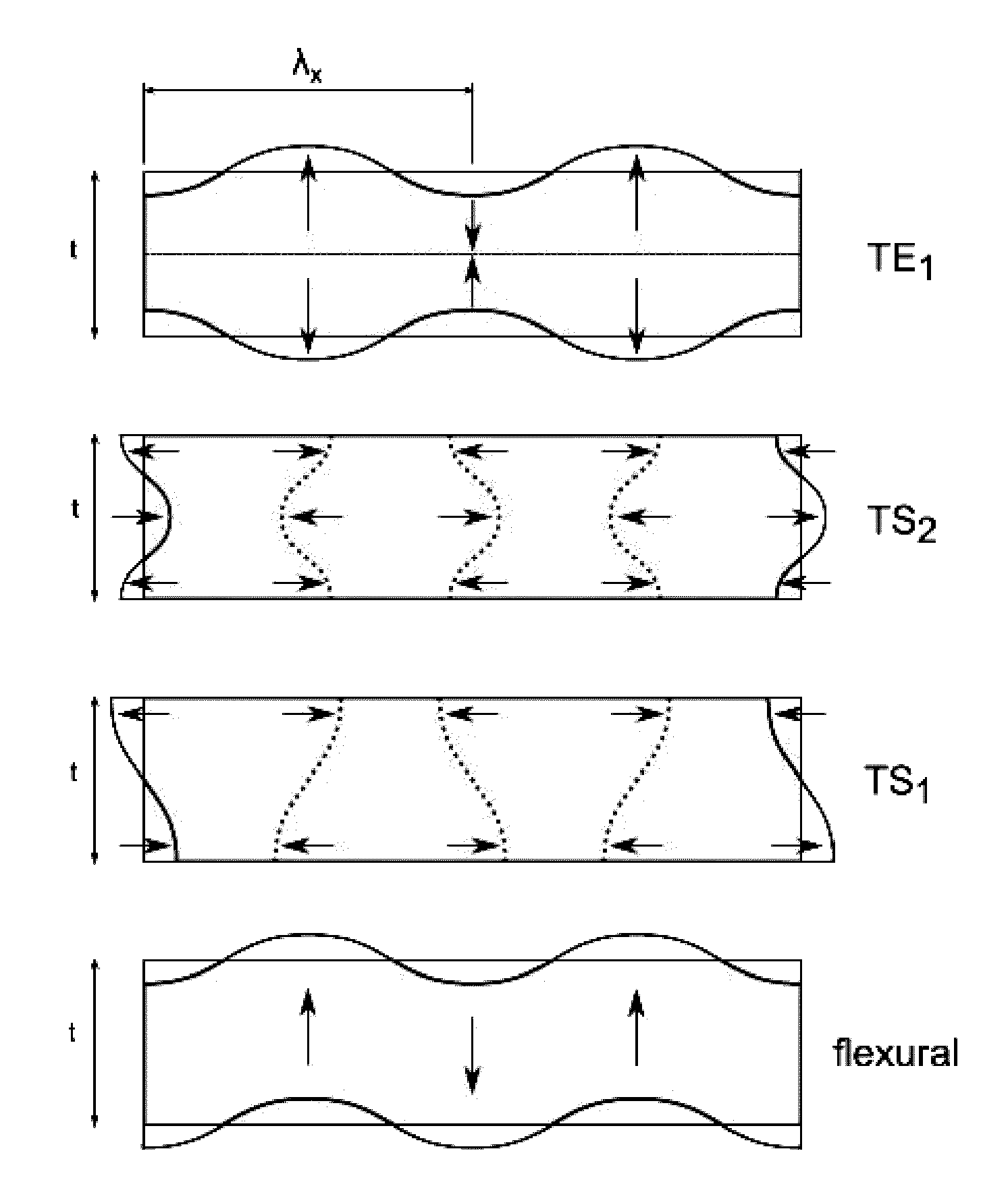
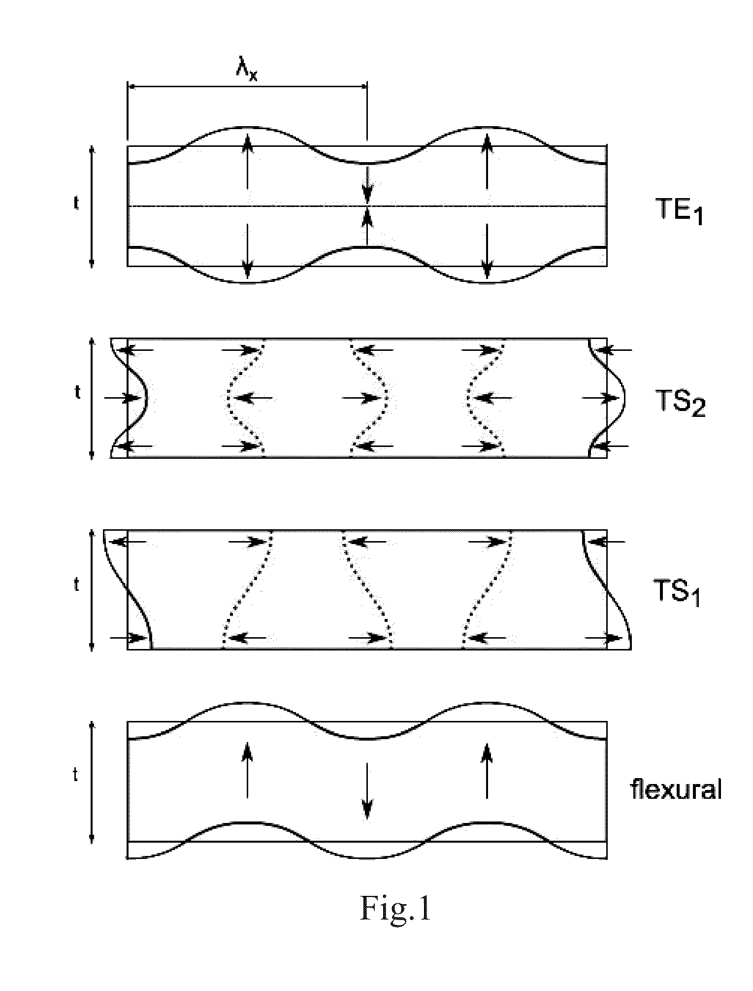
In a bulk acoustic wave (BAW) filter based on laterally acoustically coupled resonators on piezoelectric thin films, one can utilize two distinct acoustic plate wave modes of different nature, for example the thickness extensional (longitudinal) TE1 and the second harmonic thickness shear (TS2) mode to form a bandpass response. The invention is based on the excitation of at least two lateral standing wave resonances belonging to different plate wave modes that facilitate the transmission of signal. The passband is designed by tailoring the wave propagation characteristics in the device such that the resonances are excited at suitable frequencies to form a passband of a desired shape. The bandwidth of the filter described herein may therefore be more than twice that of the existing state-of-the-art microacoustic filters. Consequently, it has significant commercial and technological value.

Description

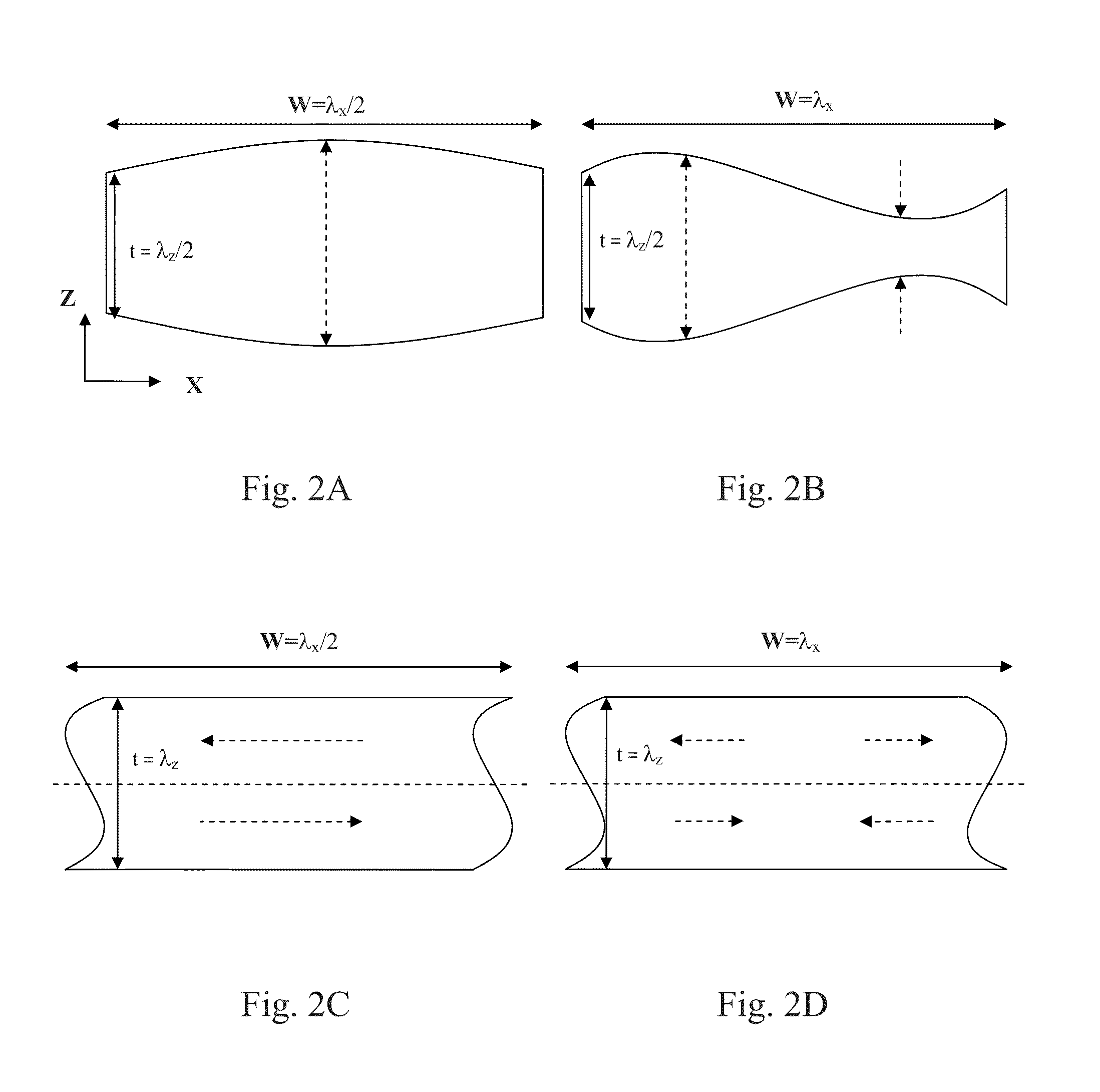
FIELD OF INVENTION[0001]The present invention relates generally to bulk acoustic wave (BAW) filters. More specifically, to wide-band acoustically coupled bulk acoustic wave filters. In particular, to those operating at GHz frequencies and based on thin-film technology and piezoelectric thin films.BACKGROUND OF THE INVENTION[0002]Some central concepts used in the following text are briefly defined here.[0003]Laterally Propagating Plate Wave Modes[0004]Bulk acoustic thickness vibration arising in a piezoelectric plate (a wafer or a thin film layer) can propagate laterally (in the horizontal direction) in the plate. Such laterally propagating wave modes are called plate wave modes or Lamb wave modes [1]. The term plate wave mode will be used here. The wave propagates with a lateral wavelength λx and has a lateral wave number kx.[0005]Different types of thickness vibration can propagate as plate waves. Examples of such vibration types are the thickness-extensional (TE) and thickness-she...

Claims


Application Information

Patent Timeline
Patent Type & Authority Applications(United States)
IPC IPC(8): H03H9/54
CPCH03H9/02228H03H9/564H03H9/0095H03H9/02007Y10T29/42H03H9/175H03H9/177H03H9/584H03H2003/0414H03H9/02125H03H9/0014H03H9/02015H03H9/205
Inventor MELTAUS, JOHANNAPENSALA, TUOMAS
Owner TEKNOLOGIAN TUTKIMUSKESKUS VTT
Why Eureka
Try Eureka