Estimating energy savings and carbon offsets for buildings in real-time

a real-time, energy-saving technology, applied in the direction of instruments, heat measurement, calorimeters, etc., can solve the problems of affecting the the difficulty of accurately estimating the energy consumption of buildings, and the difficulty of properly sized hvac systems, etc., to achieve the effect of monitoring the real-time energy performance of buildings, cost-effective, and easy implementation

Inactive Publication Date: 2013-03-07
SANTA CLARA UNIVERSITY
View PDF3 Cites 84 Cited by
  • Summary
  • Abstract
  • Description
  • Claims
  • Application Information

AI Technical Summary

Benefits of technology

[0017]The model may be implemented as a tool to monitor real-time energy performance of a building; it also can be useful for sustainability rating systems based on demonstrated performance rather than intended performance. Other applications include measurement of carbon emissions and offsets from residential buildings and sizing of HVAC systems. The techniques can also be applied to the exchang...

Problems solved by technology

Energy used by heating, ventilation, and air-conditioning (HVAC) systems in buildings also represents a significant operating cost of buildings.
For example, oversizing or undersizing of HVAC systems can result in inefficiencies.
It is currently difficult, however, to accurately estimate the heating and cooling demands for a particular building and properly size an HVAC system.
Currently, energy performance of buildings may be estimated using complex commercial energy simulation tools.
The building load estimates in Cho and Haberl, however, are based on long-term climate records, which leads to large error (oversizing or undersizing) in the sizing of HVAC systems.
Cho and Haberl is also limited to heating loads.
However, it does not estimate energy and/or carbon savings, and does not determine the thermal properties of the building.
Further, their methodology has...

Method used


Image

  • Estimating energy savings and carbon offsets for buildings in real-time
  • Estimating energy savings and carbon offsets for buildings in real-time
  • Estimating energy savings and carbon offsets for buildings in real-time

Examples


Embodiment Construction

[0029]In the description that follows, the following nomenclature will be used.

[0030]A Building inside / outside heat transfer surface area (m2)

[0031]Ac Conduit cross sectional area (m2)

[0032]E Efficiency

[0033]EA Energy rate consumption of appliances (W)

[0034]Ėtother Energy rate from other unaccounted energy sources (W)

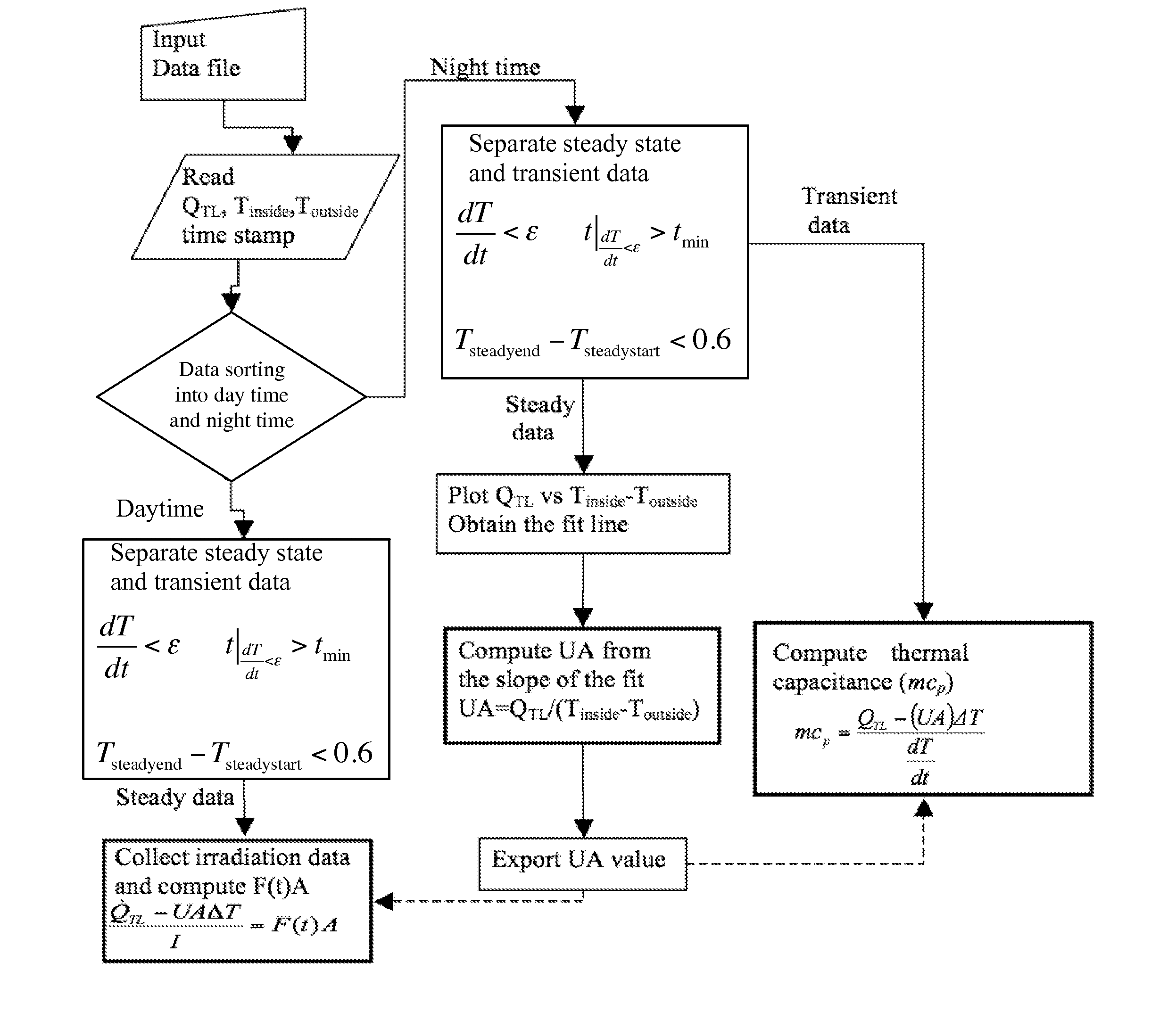
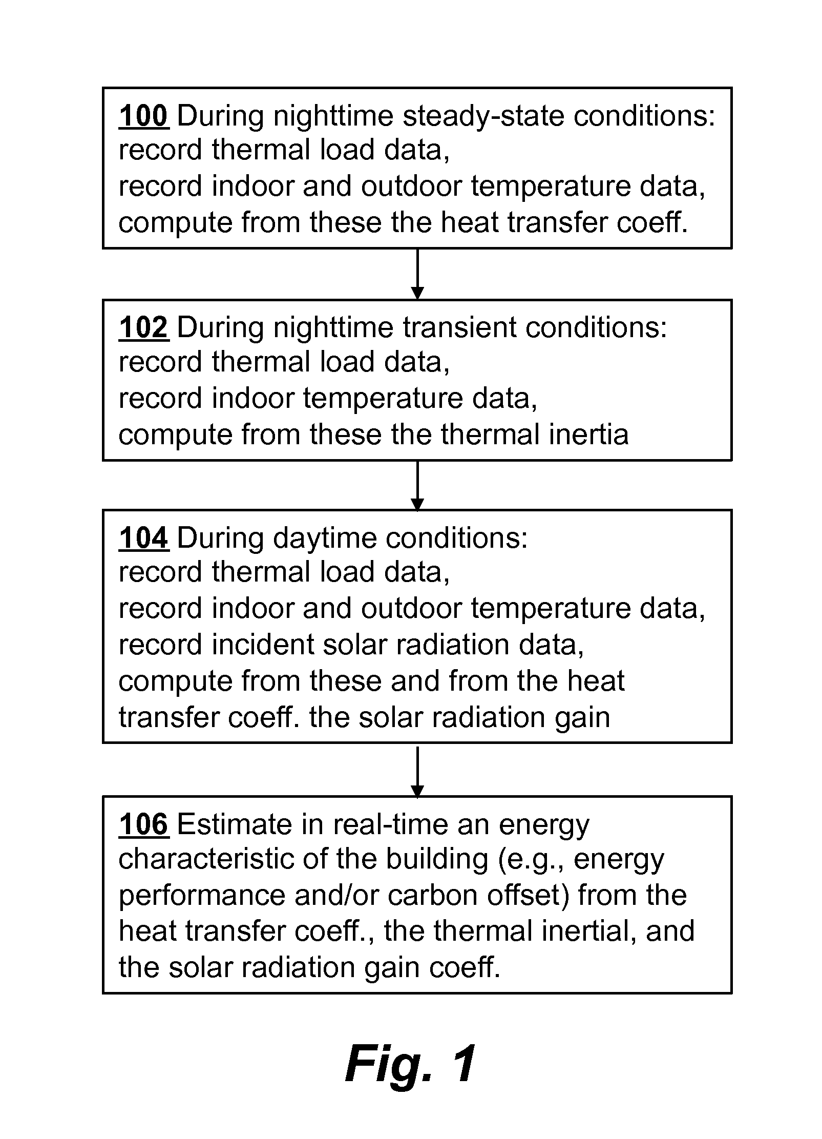
[0035]F(t) Overall solar radiation gain coefficient (radiation response) of the building

[0036]I instantaneous incident radiation on the building (W / m2)

[0037]{dot over (Q)} Energy rate (W)

[0038]{dot over (Q)}TL building thermal load

[0039]T Temperature (° C.)

[0040]ΔT temperature difference between the building indoors and outdoors

[0041]U Overall heat transfer coefficient (W / m2K)

[0042]V Velocity (m / s)

[0043]cp Building air specific heat at constant pressure (J / kgK)

[0044]t Time (s)

Tt

rate of change of the building air temperature (T) change with time (t)

[0045]m building air mass

[0046]{dot over (m)} Mass flow rate (kg / s)

[0047]mcp thermal capacitance (or thermal mass / inertia) o...


PUM


Abstract

Real-time monitoring of an energy characteristic of a building such as an energy performance of the building or a carbon offset of the building is performed by first computing a heat transfer coefficient of the building from nighttime steady-state thermal load data of the building and from nighttime steady-state indoor and outdoor temperature data of the building. A thermal inertia of the building is then computed from nighttime transient indoor temperature data of the building and nighttime transient thermal load data of the building. During daytime, a solar radiation gain coefficient is computed from daytime thermal load data, daytime indoor and outdoor temperature data, incident solar radiation data, and the heat transfer coefficient. The energy characteristic of the building is then estimated in real time from the heat transfer coefficient, the thermal inertia, and the solar radiation gain coefficient.

Description

CROSS-REFERENCE TO RELATED APPLICATIONS[0001]This application is a continuation-in-part of U.S. patent application Ser. No. 13 / 185,922 filed Jul. 19, 2011, which claims priority from U.S. Provisional Patent Application 61 / 399,947 filed Jul. 19, 2010, both of which are incorporated herein by reference.FIELD OF THE INVENTION[0002]The present invention relates to systems and methods for real-time determination of energy characteristics and thermal characteristics of buildings.BACKGROUND OF THE INVENTION[0003]Methods for evaluation of the energy performance of residential buildings are of importance for many reasons including the need to reduce emissions of greenhouse gases (GHGs). Energy used by heating, ventilation, and air-conditioning (HVAC) systems in buildings also represents a significant operating cost of buildings. To reduce such energy consumption, energy inefficiencies can be identified and measures taken to make a building and its HVAC system more energy efficient. Improved ...

Claims


Application Information

Patent Timeline
IPC IPC(8): G01K17/00G01W1/00G06F15/00
CPCG01K17/00
Inventor ASCHHEIM, MARK A.GONZALES CRUZ, JORGE E.MAURER, EDWIN P.ESCOBAR-VARGAS, SERGIO
Owner SANTA CLARA UNIVERSITY
Why Eureka
Try Eureka