
Functional laminated plate, and transparent electrically conductive laminated plate for touch panel and touch panel produced using same

a technology of laminated plate and touch panel, which is applied in the direction of instruments, other domestic articles, synthetic resin layered products, etc., can solve the problems of sheet cracking in die cutting processing, lack of stiffness of functional films when used alone, and low flexibility, so as to achieve good die cutting workability, small thickness, and strong stiffness

Inactive Publication Date: 2013-03-14
KIMOTO CO LTD
View PDF3 Cites 38 Cited by
  • Summary
  • Abstract
  • Description
  • Claims
  • Application Information

AI Technical Summary

Benefits of technology

The present invention relates to a functional laminated plate and a transparent electrically conductive laminated plate for a touch panel. The laminated plate has a structure in which at least two plastic films are adhered to each other through an adhesive layer. This results in a thin, strong, and easily handleable plate with good die cutting workability. The laminated plate is also less likely to crack because the plastic film acts as a shock absorber. The transparent electrically conductive laminated plate for a touch panel is lightweight and has no risk of damage during handling. It provides stiffness and tactile sensation while being lightweight and safe from glass scattering during handling.

Problems solved by technology

Since these functional films lack in stiffness when used alone, they are used by being adhered to a reinforcing sheet such as a plastic sheet.
Although a functional laminated plate including a functional film adhered to a plastic sheet has favorable stiffness, the flexibility is low because the thickness is large.
Furthermore, another problem occurs in that the sheet cracks in die cutting processing for obtaining a desired size.
A functional plastic sheet including a functional layer directly formed on a plastic sheet has a similar problem.
Bonding a functional film on, or forming a functional layer on a plastic sheet which already has a predetermined size is an idea for avoiding the problem with the die cutting processing; however, this idea leads to a problem of lower workability.
However, the use of glass as the transparent base leads to problems of larger weight and higher risk of scattering when the glass is damaged.
A transparent electrically conductive laminated plate including a plastic sheet with sufficient thickness as the transparent base has sufficient stiffness; however, problems occur in that the stiffness is too high to secure tactile sensation (touch sensitivity) and that the sheet cracks in die cutting processing for obtaining a desired size.
Even in this case, forming a transparent electrically conductive layer on a transparent plastic sheet which already has a predetermined size is considered for avoiding the problems in the die cutting processing; however, this leads to a problem of lower workability.

Method used


Image

  • Functional laminated plate, and transparent electrically conductive laminated plate for touch panel and touch panel produced using same
  • Functional laminated plate, and transparent electrically conductive laminated plate for touch panel and touch panel produced using same
  • Functional laminated plate, and transparent electrically conductive laminated plate for touch panel and touch panel produced using same

Examples


embodiment 1

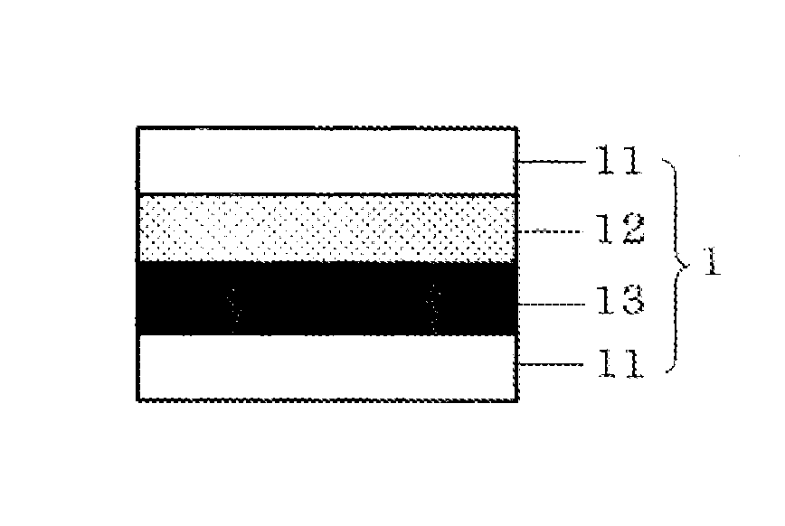
[0063]A functional laminated plate according to Embodiment 1 includes at least one functional layer between a plastic film and a plastic film. Specific examples thereof are described with reference to FIG. 1 to FIG. 4. In FIG. 1 and FIG. 2, the number of plastic films is two; in FIG. 3 and FIG. 4, the number of plastic films is three. Although depending on the purpose or film-formation method of the functional layer, the position of a functional layer 13 in a laminated plate 1 may be between a plastic film 11 and an adhesive layer 12 as depicted in FIG. 1 or FIG. 3, or may be between the adhesive layers 12 as depicted in FIG. 2 or FIG. 4. Since the functional laminated plate according to this embodiment includes the functional layer inside the laminated plate, the functional layer can be prevented from being damaged and the durability thereof can be improved.

[0064]As the functional layer of this embodiment, a layer having a function selected from an electromagnetic wave shielding fu...

embodiment 2

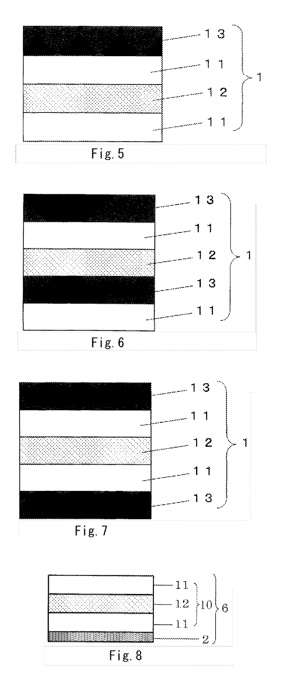
[0083]A functional laminated plate according to Embodiment 2 includes a functional layer on at least one surface of a plastic film on the outermost surface. Examples thereof are shown in FIG. 5 to FIG. 7. FIG. 5 and FIG. 6 show the case where the functional layer 13 is provided on one outermost surface of the functional laminated plate 1, and FIG. 7 shows the case where the functional layer 13 is provided on each outermost surface of the functional laminated plate 1. In addition to the functional layer 13 provided on the outermost layer, another functional layer 13 may be provided inside the laminated plate as shown in FIG. 6. Although FIG. 5 to FIG. 7 depict the laminated plate including the two plastic films 11, the laminated plate may include three or more plastic films as shown in FIG. 3 or FIG. 4 according to Embodiment 1. Alternatively, the functional layer can be attached to the uppermost plastic film through the adhesive layer 12.

[0084]As the functional layer according to th...

embodiment 3

[0110]In Embodiment 3 that describes a transparent electrically conductive laminated plate for a touch panel, a transparent electrically conductive layer is provided on at least one surface of a transparent laminated plate. Specific examples thereof are shown in FIG. 8 to FIG. 10.

[0111]FIG. 8 depicts a transparent electrically conductive laminated plate 6 for a touch panel including a transparent electrically conductive layer 2 on one surface of a transparent laminated plate 10, which can be used for an upper electrode or a lower electrode of a resistive touch panel or for a member of an electrostatic capacitive touch panel of a surface type. FIG. 9 depicts the transparent electrically conductive laminated plate 6 for a touch panel including the transparent electrically conductive layer 2 on each surface of the transparent laminated plate 10, which can be used for an electrostatic capacitive touch panel of a projection type, or an electrostatic capacitive touch panel of a surface ty...


PUM

PropertyMeasurementUnit
Lengthaaaaaaaaaa
Lengthaaaaaaaaaa
Thicknessaaaaaaaaaa

Abstract

Disclosed is a functional laminated sheet having flexibility, high body and good die cutting workability. The functional laminated sheet comprises a laminated sheet composed of at least two plastic films bound to each other through an adhesive layer and a functional layer formed on one surface or both surfaces of at least one of the plastic films, wherein the adhesive layer has a Martens hardness of 260 N / mm2 or less. The functional layer is, for example, a layer having an electromagnetic wave shielding function, a heat ray reflection function, a gas barrier function or a planar heat generation function, and can be arranged in the inside of the laminated sheet. Alternatively, the functional layer is a layer having a light reflection function, a light permeation control function or an antifogging function, and can be arranged on the outermost surface of the laminated sheet. Also disclosed is a transparent electrically conductive laminated sheet for a touch panel, which comprises a transparent laminated sheet having a transparent plastic film bonded thereto through the adhesive layer and a transparent electrically conductive layer formed on the transparent laminated sheet.

Description

[0001]This application is a U.S. national phase filing under 35 U.S.C. §371 of PCT Application No. PCT / JP2011 / 054151, filed Feb. 24, 2011, and claims priority under 35 U.S.C. §119 to Japanese patent application nos. 2010-047259; 2010-047258 and 2010-047257, all filed Mar. 4, 2010, the entireties of all of which are incorporated herein by reference.TECHNICAL FIELD[0002]The present invention relates to a functional laminated plate and to the one having stronger stiffness while having smaller thickness, in which a plastic film can be prevented from separating off from an adhesive layer during die cutting processing. Moreover, the present invention relates to a transparent electrically conductive laminated plate for a touch panel with excellent workability (die cutting processing), which is lightweight and has no risk of damage, and to a touch panel including the same.BACKGROUND ART[0003]In recent years, a variety of functional films have appeared such as an electromagnetic wave shieldi...

Claims


Application Information

Patent Timeline
IPC IPC(8): B32B27/00G06F3/044G06F3/045B32B7/02B32B7/023B32B7/025
CPCB32B7/02B32B7/12B32B27/08B32B2457/208G06F3/044G06F3/045Y10T428/2495B32B27/36B32B2255/10B32B2255/20B32B2255/205B32B2255/26B32B2307/40B32B27/00Y10T428/31504G06F3/0445G06F3/0446B32B7/023B32B7/025
Inventor KURISHIMA, SUSUMUNEGISHI, SATOSHIHASEGAWA, TAKESHIAIKAWA, TAKAYUKITAKAHASHI, KOJIUSHIO, SEIJI
Owner KIMOTO CO LTD
Learn More