Ink set for forming multilayer, ink jet recording method, and printed material

a multi-layer, ink jet recording technology, applied in the direction of inks, instruments, transportation and packaging, etc., can solve the problems of sometimes occurring gloss differences, achieve excellent blocking resistance, excellent image quality and glossiness, and satisfactory surface condition

Active Publication Date: 2013-03-14
FUJIFILM CORP
View PDF1 Cites 17 Cited by
  • Summary
  • Abstract
  • Description
  • Claims
  • Application Information

AI Technical Summary

Benefits of technology

[0028]According to the present invention, an ink set for forming a multilayer which has excellent image quality and glossiness, gives a satisfactory surface condition, has excellent blocking resistance, and may form an image with small

Problems solved by technology

In particular, up to now, in an ultraviolet ray curable ink jet ink printer using clear ink, gloss differences have sometimes occurred since a sati

Method used


Image

  • Ink set for forming multilayer, ink jet recording method, and printed material
  • Ink set for forming multilayer, ink jet recording method, and printed material
  • Ink set for forming multilayer, ink jet recording method, and printed material

Examples


specific examples

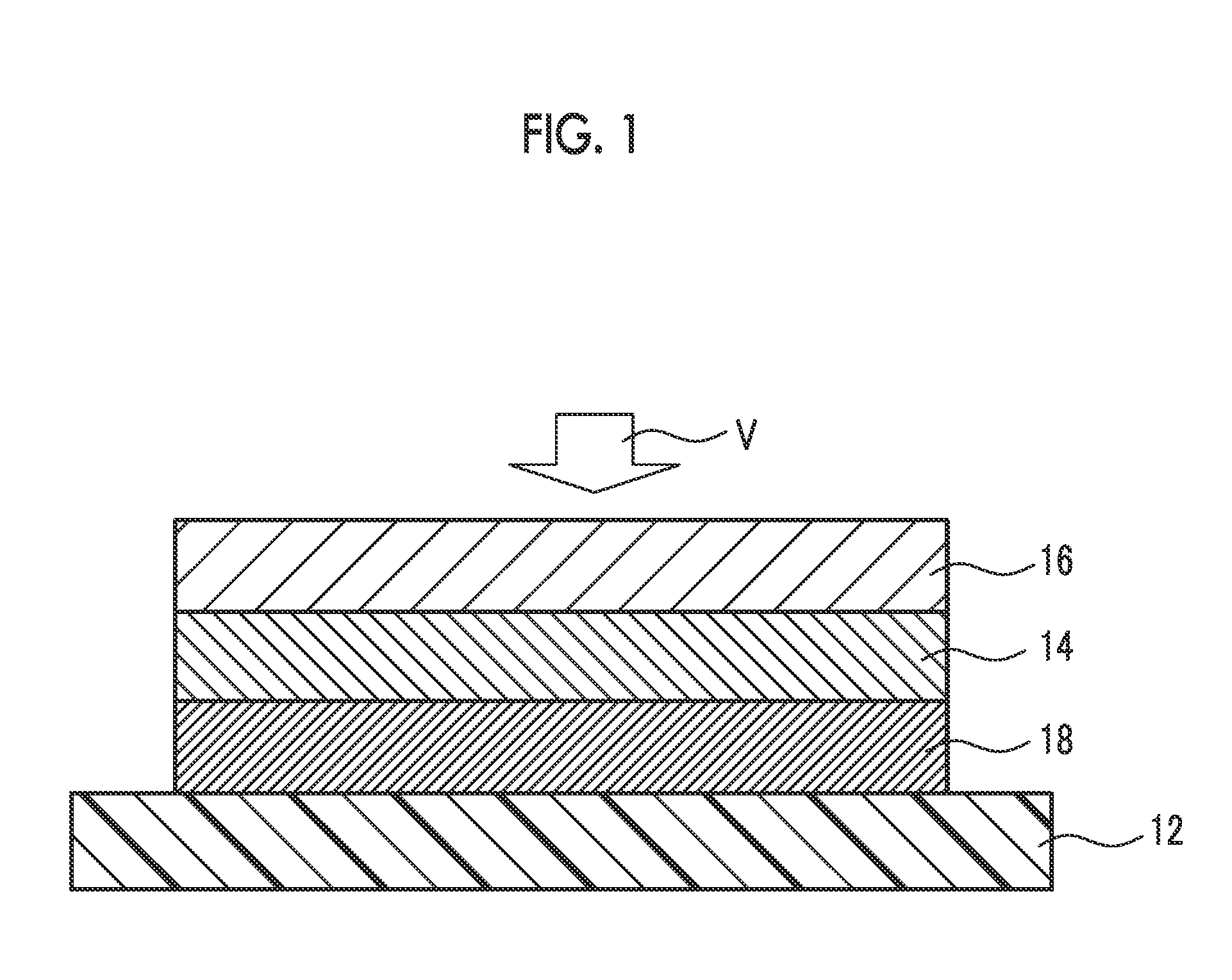
[0331]In the image shown in FIG. 1, the number of image forming layers is 2, the image layer 14 is formed on the reflective recording medium 12 and the clear ink layer 16 is formed on the image layer 14. In the Image having such a structure, the image layer 14 can be visually recognized with a background of the reflective recording medium 12 or arbitrary white layer 18 when viewed from the V direction.

[0332]Hereinafter, description will be made with reference to FIG. 6. In order to obtain a high gloss by stacking the clear ink layer on top of the image layer, the head used for forming the image layer uses a head of the upstream side of Y, M, C, K, LC and LM, and the light sources (32A-1 and 32B-1) on both sides thereof form the image layer with the lamp set to be ON. After that, the head used to form the clear ink layer uses a head 61CL at the downstream side of CL, and the lamp of the light sources (32A-2 and 32B-2) on both sides thereof is set to be OFF, and as a result, time for ...

examples

[0373]Hereinafter, examples and comparative examples are shown and the present invention is described in more detail. However, the present invention is not limited to these examples. In addition, “parts” represents “parts by mass” and “%” represents “mass %” unless otherwise specified.

[0374](Preparation of Yellow Mill Base)[0375]Yellow pigment: NOVOPERM YELLOW H2G (manufactured by Clariant International Ltd.) 30 parts by mass[0376]SR9003 (propoxylated (2) neopentyl glycol diacrylate (a compound in which 2 mol adduct of neopentyl glycol propylene oxide is diacrylated), manufactured by SARTOMER Company) 30 parts by mass[0377]BYK168 (a dispersing agent, manufactured by BYK-Chemie GmbH) 40 parts by mass

[0378]The components described above were stirred and a yellow mill base was obtained. In addition, preparation of the pigment mill base was made by placing the yellow mill base in a disperser motor mill M50 (manufactured by EIGER Machinery, Inc.) and dispersing at peripheral speed of 9 m...


PUM

PropertyMeasurementUnit
Percent by massaaaaaaaaaa

Abstract

An ink set for forming a multilayer of the present invention includes a group of coloring ink compositions which include a yellow, a magenta, a cyan and a black ink composition, and a clear ink composition, wherein each of the coloring ink compositions contain a (component A) radical polymerizable compound, a (component B) radical polymerization initiator and a (component D) coloring agent, and the component A contains a (component A-1) N-vinyl compound and a (component A-2) specific ethylenic unsaturated compound (CTFA), the clear ink composition contains a (component A) radical polymerizable compound, a (component B) acylphosphine oxide-based photoinitiator and a (component C) surfactant, and the relation of 0.1≦(Y/X)<1 is satisfied when the content of the radical polymerization initiator in the clear ink composition is X, the content of the radical polymerization initiator in the magenta ink composition is Y.

Description

BACKGROUND OF THE INVENTION[0001]1. Field of the Invention[0002]The present invention relates to an ink set for forming a multilayer, an ink jet recording method, and a printed material.[0003]2. Description of the Related Art[0004]As an image recording method in which an image is formed on a recording medium such as paper based on image data signals, there are an electrophotographic method, a sublimation type and a melt type thermal printing method, an ink jet recording method, and the like.[0005]In ink jet methods, printing devices are low-priced, no plates are needed when printing, and ink compositions may be efficiently used since an image is directly formed on a recording medium by discharging the ink composition to only necessary image parts, therefore, running costs are low especially in the case of small-lot productions. In addition, ink jet methods have low noise and are excellent imaging recording methods, and as a result, have been receiving attention in recent years.[0006...

Claims


Application Information

Patent Timeline
IPC IPC(8): C09D11/10B41J29/38B32B3/10B41J2/01B41M5/00C09D11/00C09D11/326C09D11/328C09D11/38C09D11/40
CPCY10T428/24802C09D11/40C09D11/101
Inventor MOCHIZUKI, KYOHEIFUJII, YUSUKEARAKI, KENJIROU
Owner FUJIFILM CORP
Why Eureka
Try Eureka