Catalyst layer material, method for fabricating the same, and fuel cell

a catalyst layer and fuel cell technology, applied in the field of electrochemical techniques, can solve the problems of increasing environmental destruction, affecting the performance and stability of the fuel cell, and the importance of the catalyst support in the anode catalyst layer or the cathode catalyst layer is often neglected, so as to achieve outstanding enhancement of stability and active performance of the fuel cell, and the effect of preventing corrosion of the conventional carbonaceous catalyst suppor

Active Publication Date: 2013-03-14
NAT TAIWAN UNIV OF SCI & TECH
View PDF5 Cites 2 Cited by
  • Summary
  • Abstract
  • Description
  • Claims
  • Application Information

AI Technical Summary

Benefits of technology

[0032]As mentioned above, in the present invention, the non-carbonaceous catalyst support is utilized in the catalyst layer material and the fabrication thereof that can be applied to the fuel cell, and thereby the problems regarding corrosion of the conventional carbonaceous catalyst support can be practically prevented. Accordingly, stability and active performance of the fuel cell can be outstandingly enhanced. Besides, metal elements contained in the catalyst support are properly chosen with high conductivity. Thus, the catalyst support can not only function as a material with high current conduction but as a co-catalyst in cooperative catalysis, and kinetic current of electrochemical reactions is also increased.

Problems solved by technology

The conventional techniques for exploiting and applying energy sources, however, lead to increasing environmental destruction.
In the fuel cell, importance of a catalyst support in the anode catalyst layer or the cathode catalyst layer is often neglected.
In the actual application of the conventional fuel cell, the carbonaceous catalyst-support is, nevertheless, prone to corrosion in particular under repeated start-stop cycles or high-potential conditions, which may dramatically impact on performance and stability of the fuel cell.

Method used


Image

  • Catalyst layer material, method for fabricating the same, and fuel cell
  • Catalyst layer material, method for fabricating the same, and fuel cell
  • Catalyst layer material, method for fabricating the same, and fuel cell

Examples


example 1

Preparation of Pt / Ti0.7Ru0.3O2

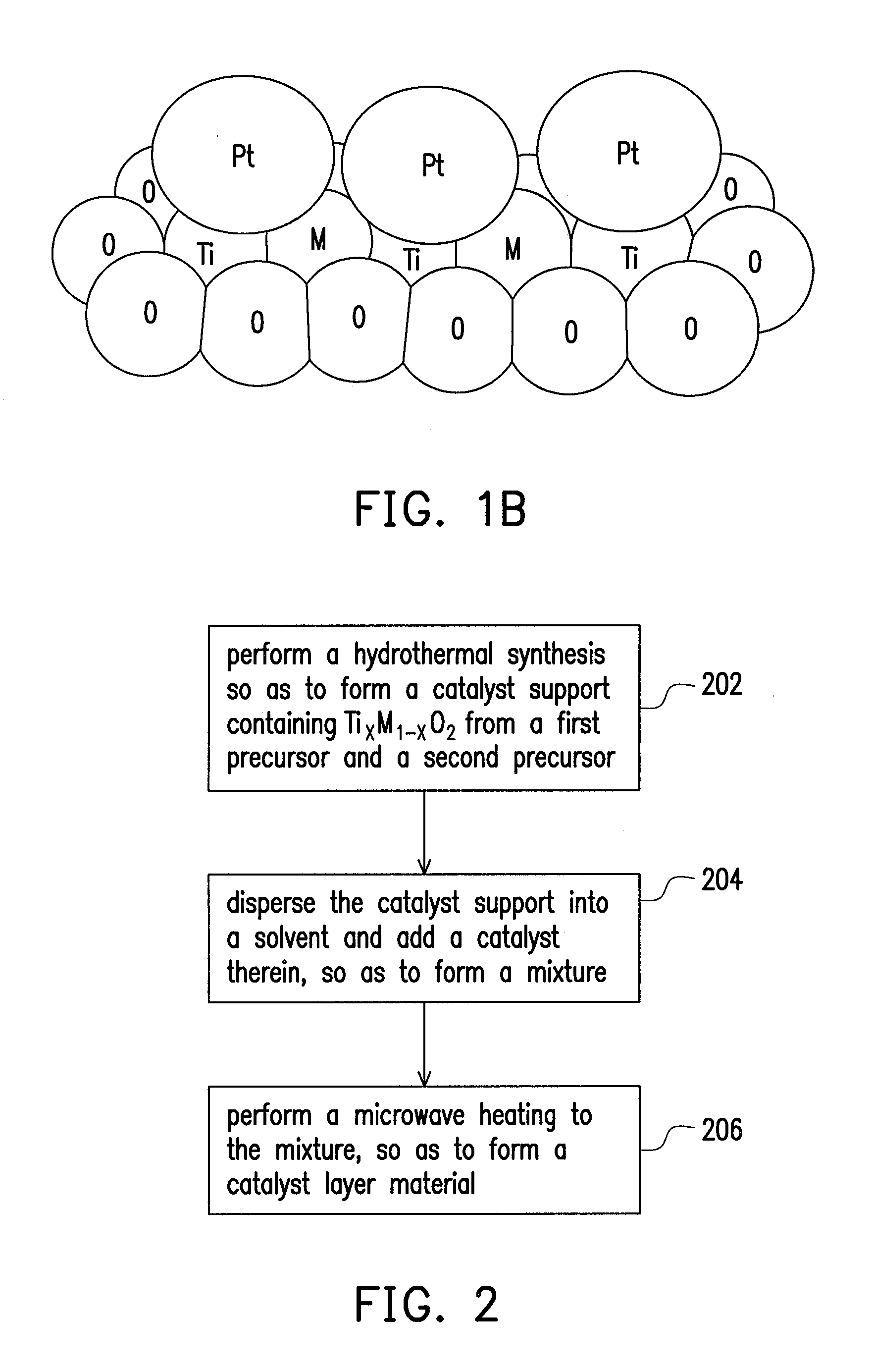
[0061]Ti0.7Ru0.3O2 nanoparticles were prepared as following: an aqueous solution containing 12 mM RuCl3 and 28 mM TiCl4 precursors solution (with molar ratio of Ru:Ti=3:7) was prepared. Then, 1 mL H2O2 30 wt % in water was added into the RuCl3 solution to oxidize Ru+3 to Ru+4 before mixing with TiCl4 solution. The uniformity of the mixing constituents of the dispersion may be enhanced by stirring for 15 minutes. The precursor solution was transferred to a Teflon-lined autoclave with a stainless steel shell and heated to 200° C. at 10° C. / min. The reaction was kept at 200° C. for 2 hours in the oven and then cooled to room temperature. After finishing the reaction, the suspension was washed with water and collected by centrifugation several times until the washings showed pH 7. The precipitates were dried in a vacuum oven overnight (>8 hours) at 80° C. for the electrochemical and textural analyses.

[0062]The synthesis was carried out with the aid of a do...

example 2

Application of Pt / Ti0.7Ru0.3O2 and Pt or PtRu Alloy Catalysts on Commercial Carbonaceous Support in Direct Methanol Fuel Cell (DMFC) Anode and Comparison of Properties and Performance

[0064]In this example, the catalytic performance of the prepared Pt / Ti0.7Ru0.3O2and the commercial Pt / C (E-TEK) and PtRu / C (JM) catalysts was compared in a practical DMFC system. FIG. 4 is a curve chart illustrating performance comparison of 20 wt % Pt / C (E-TEK), 30 wt % PtRu(2:1) / C (JM) and 20 wt % Pt / Ti0.7Ru0.3O2 nano-catalysts which are respectively applied as anode catalysts of DMFC according to examples of the present invention. These DMFC systems shown in FIG. 4 were operated with 2M methanol at 60° C. under the same testing conditions (with commercial Pt / C (E-TEK) as cathode and respective nanocatalysts as anode). The Pt loading of the catalyst support was controlled at 0.5 mg / cm2 at anodic side and 0.5 mg / cm2 at the cathode side for all catalysts.

[0065]As the results demonstrated in FIG. 4, it c...

example 3

Preparation of Pt / Ti0.7Mo0.3O2

[0068]Similar to Example 1, Ti0.7Mo0.3O2 was synthesized by the hydrothermal method as follows. First, 0.155 mL of pure TiCl4 was dissolved in 30 mL of 1 M HCl, and 0.146 g of Na2MoO4.2H2O was dissolved in 20 mL of distilled water. Then, TiCl4 solution was mixed with Na2MoO4 solution, followed by stirring 30 minutes at room temperature. After that, the mixed solution was transferred to a Teflon-lined autoclave with a stainless steel shell and heated to 200° C. at 10° C. / min. The reaction time was kept at 2 hours. After finishing the reaction, the system was cooled naturally to room temperature. The as-synthesized sample of Ti0.7Mo0.3O2 was obtained after washing, centrifuge many times and drying in the oven at 80° C. overnight. So the as-synthesized Ti0.7Mo0.3O2 support can be obtained with high purity, good crystallize and fine powder under using the hydrothermal process.

[0069]The 20 wt % Pt loading was deposited on the Ti0.7Mo0.3O2 in following steps...


PUM

PropertyMeasurementUnit
temperatureaaaaaaaaaa
microwave frequencyaaaaaaaaaa

Abstract

A catalyst layer material, a method for fabricating the same, and a fuel cell are provided. The catalyst layer material utilized for the fuel cell includes a catalyst support and a catalyst distributed on the catalyst support. The catalyst support contains TixM1-xO2, wherein M is selected from the group consisting of a Group IB metal, a Group IIA metal, a Group IIB metal, a Group IIIA, a Group VB metal, a Group VIB metal, a Group VIIB metal and a Group VIIIB metal, and 0<X≦0.9. By applying the non-carbonaceous catalyst support containing high conductivity metal elements to the fuel cell, stability and performance of the cell can be effectively enhanced.

Description

CROSS-REFERENCE TO RELATED APPLICATION[0001]This application claims the priority benefit of Taiwan application serial no. 100132440, filed on Sep. 8, 2011. The entirety of the above-mentioned patent application is hereby incorporated by reference herein and made a part of this specification.BACKGROUND OF THE INVENTION[0002]1. Field of the Invention[0003]The present invention relates to an electrochemical technique, and more particularly, to a catalyst layer material, a method for fabricating the same, and a fuel cell.[0004]2. Description of Related Art[0005]Exploitation and application of energy sources are always indispensable in our daily lives. The conventional techniques for exploiting and applying energy sources, however, lead to increasing environmental destruction. Fuel cell-based power generation characterized by high efficiency, low noise and non-pollution complies with the trend and therefore is very promising in the energy industry.[0006]In brief, the fuel cell is substan...

Claims


Application Information

Patent Timeline
Patent Type & Authority Applications(United States)
IPC IPC(8): B01J21/06H01M8/10
CPCY02E60/50Y02E60/523H01M4/9075H01M4/88H01M8/1011
Inventor HO, VAN THI THANHPAN, CHUN-JERNSU, WEI-NIENHWANG, BING-JOE
Owner NAT TAIWAN UNIV OF SCI & TECH
Why Eureka
Try Eureka