At-bit magnetic ranging and surveying

a magnetic ranging and surveying technology, applied in the field of subterranean wellbore surveying, can solve the problems of affecting the operator's ability to make timely steering decisions, and affecting the accuracy of magnetic ranging and surveying measurements, so as to improve the control of the wellbore profile, improve the accuracy of placement, and reduce the latency

Active Publication Date: 2013-03-21
SCHLUMBERGER TECH CORP
View PDF4 Cites 29 Cited by
  • Summary
  • Abstract
  • Description
  • Claims
  • Application Information

AI Technical Summary

Benefits of technology

[0010]The disclosed embodiments may provide various technical advantages. For example, disclosed embodiments provide for at or near bit magnetic surveying and ranging measurements. Such near bit measurements reduce latency (the time between formation cutting and surveying or ranging measurements at that location) and thereby may enable the well driller to make steering decisions in a time fashion. Timely steering in turn may provide for improved control of the wellbore profile and may therefore further improve placement accuracy and reduce wellbore tortuosity.
[0011]Reduced latency has many other potential benefits. For example, obtaining early survey data may enhance the ability of automated drilling systems (e.g., closed loop drilling systems or payzone steering systems) to maintain the direction of drilling along a predetermined path. Moreover, near bit deployment of the survey sensors enables accurate surveys to be obtained quickly upon exiting a casing window or casing shoe and therefore may eliminate the need for making large steering corrections at a later time.

Problems solved by technology

Those of ordinary skill in the art will appreciate that such a deployment increases the time between cutting (drilling) and ranging at a particular location which in turn hinders an operator's ability to make timely steering decisions.
One difficulty in deploying magnetic sensors at or near the drill bit is that the lower BHA is generally highly magnetic (particularly the drill bit and motor) and can therefore strongly interfere with magnetic ranging and surveying measurements.

Method used


Image

  • At-bit magnetic ranging and surveying
  • At-bit magnetic ranging and surveying
  • At-bit magnetic ranging and surveying

Examples


Embodiment Construction

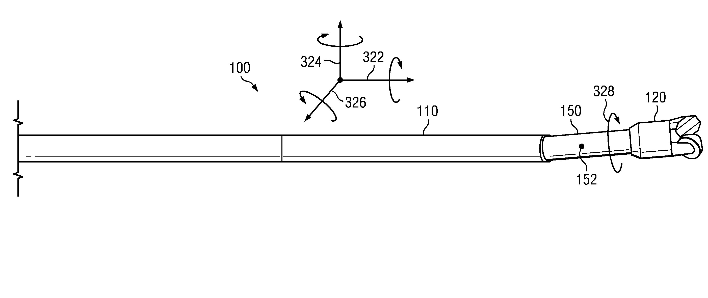
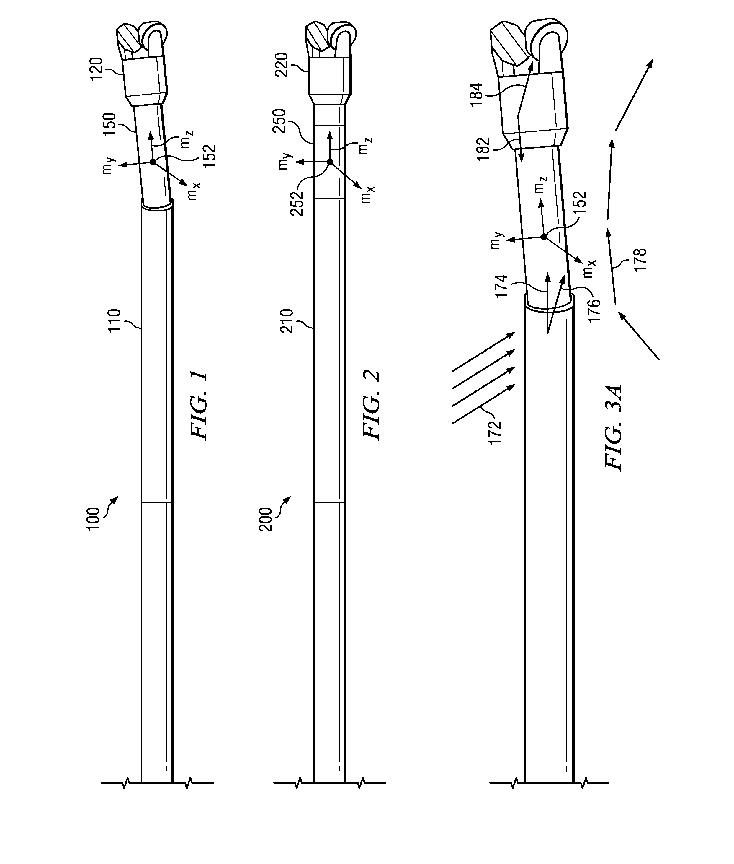
[0026]FIG. 1 depicts one example of a BHA embodiment 100 including a drilling motor 110 deployed above a bent sub 115. A sensor sub 150 including a magnetic field sensor 152 is deployed axially between the drilling motor 110 and a drill bit 120. FIG. 2 depicts an alternative BHA embodiment 200 including a sensor sub 250 including a magnetic field sensor 252 deployed axially between a steering tool 210 such as a rotary steerable tool and a drill bit 220. In the embodiments depicted on FIGS. 1 and 2, the sensor subs 150 and 250 are configured to rotate about a longitudinal axis of the BHA 100 and 200 with the drill bit 120 and 220. The magnetic sensors 152 and 252 may include substantially any magnetic sensors suitable for downhole deployment such as conventional tri-axial magnetometer deployments.

[0027]It will be understood that the embodiments depicted on FIGS. 1 and 2 are merely examples in that they depict the deployment of the magnetic field sensors substantially at the drill bit...


PUM


Abstract

A bottom hole assembly configured for a subterranean drilling operation having a drill bit; a downhole tool deployed above the drill bit, at least a portion of the downhole tool free to rotate with respect to the drill bit about a longitudinal axis of the bottom hole assembly a sensor sub deployed axially between the drill bit and the downhole tool, the sensor sub configured to rotate with the drill bit about the longitudinal axis of the bottom hole assembly and free to rotate with respect to the downhole tool about the longitudinal axis and a tri-axial magnetic field sensor deployed in the sensor sub.

Description

CROSS REFERENCE TO RELATED APPLICATIONS[0001]This application claims the benefit of U.S. Provisional Application Ser. No. 61 / 508,732 entitled At-Bit Magnetic Ranging and Surveying, filed Jul. 18, 2011.FIELD OF THE INVENTION[0002]Disclosed embodiments relate generally to surveying subterranean wellbores used for oil and natural gas exploration and production. In particular, they relate to a method and apparatus for making near-bit or at-bit magnetic ranging and / or surveying measurements while drilling. Such ranging measurements may be utilized, for example, in twin well drilling operations such as in steam assisted gravity drainage (SAGD) and horizontal to vertical well intercept operations such as used in coal bed methane (CBM).BACKGROUND INFORMATION[0003]Magnetic field measurements may be used in downhole surveying operations to determine the direction of the Earth's magnetic field at a particular point (or survey station). Magnetic field measurements may also be used to locate sub...

Claims


Application Information

Patent Timeline
Patent Type & Authority Applications(United States)
IPC IPC(8): G01V3/26
CPCE21B47/02216G01V3/26E21B47/0228E21B47/022G01V3/18
Inventor MCELHINNEY, GRAHAM A.CEH, LEONSTENERSON, KENNETHFORBES, EUAN
Owner SCHLUMBERGER TECH CORP
Why Eureka
Try Eureka