
Magnetic recording head and magnetic recording apparatus

a recording head and magnetic recording technology, applied in the direction of magnetic recording heads, data recording, instruments, etc., can solve the problems of insufficient magnetization switching speed of reference layer lamination, inability to improve linear areal recording density, and extremely difficult realization

Inactive Publication Date: 2013-03-21
HITACHI LTD
View PDF9 Cites 20 Cited by
  • Summary
  • Abstract
  • Description
  • Claims
  • Application Information

AI Technical Summary

Benefits of technology

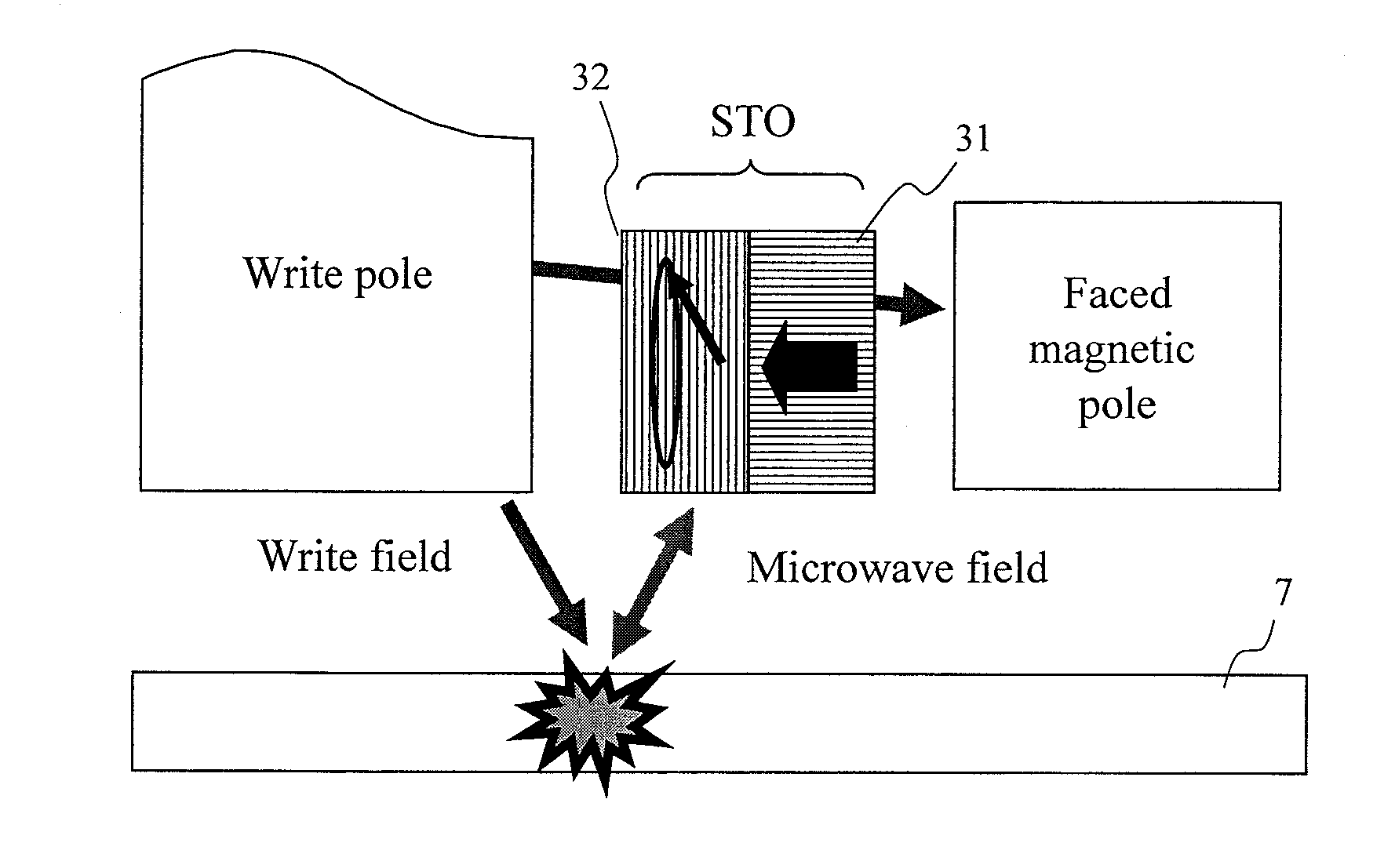
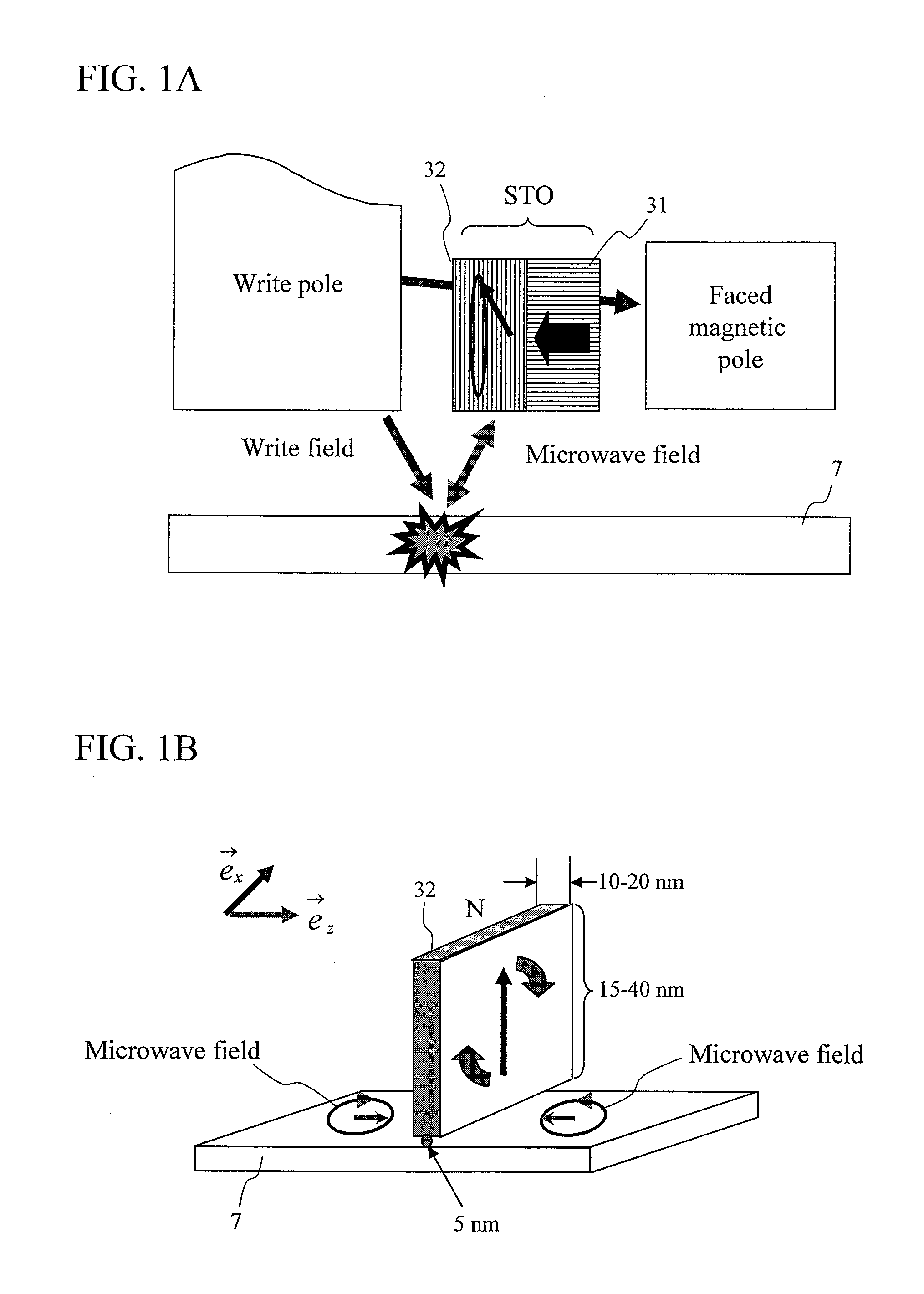
The present invention is about a magnetic recording head and a magnetic recording apparatus that can write to ultra-high density magnetic recording media quickly and reliably. The invention solves the problem of slow and unstable oscillation of the main pole during magnetization switching, which makes it difficult to increase the oscillatory frequency and apply a large STO drive current. The spin torque oscillator uses a reference layer for synchronizing the magnetization of the main pole and the FGL, which reduces the time needed for stable oscillation state. The rotation state of the applied magnetic field can be quickly switched, resulting in high information transfer rates. In summary, the invention allows for faster and more reliable magnetic recording using the microwave assisted recording method with areal recording density exceeding 1 T bit per square inch.

Problems solved by technology

If the rotating direction of magnetization of the FGL is not switched every time polarity of the main pole is switched, a switching position of medium magnetization will shift before and behind the FGL, and linear areal recording density cannot be improved.
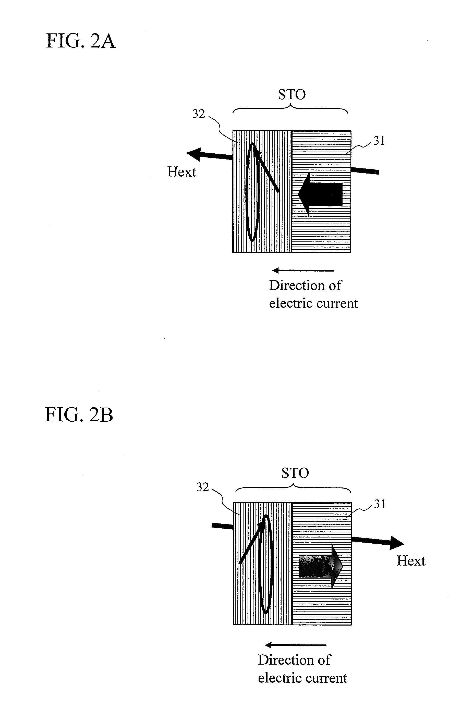
In this case, the following problems need to be solved, which thus makes realization extremely difficult: a) efficiency of spin torques varies depending on whether a current is positive or negative, b) external magnetic fields to be applied to the FGL are not equal, c) a rising angle of FGL magnetization differs, and d) STO drive currents need to be synchronized with magnetic fields of a main pole
The multilayer such as (Co / Pd)n, (Co / Pt)n and the like whose magnetic coercive force is reduced tends to have further reduced saturation flux density B. Thus, even lamination of high Bs materials cannot achieve sufficient magnetization switching speed of the reference layer.
In addition, there is another problem that due to low magnetic coercive force of the reference layer, when an attempt is made to supply large spin torques to the FGL by intensifying electric currents, counteraction thereof destabilizes the reference layer magnetization.
Furthermore, there is also a problem that as the multilayer has a high damping factor α of 0.1 to 0.3 for magnetization motion, spins are consumed by the spin pumping action, and consequently, application of more electric currents is necessary to obtain high-frequency magnetic fields of same frequency.
However, magnetization of the reference layer easily fluctuates due to effect of magnetization state of the main pole or counteraction of spin torques from the FGL, which makes it difficult to apply a large STO drive current and increase an oscillatory frequency.
Thus, there is a concern that sufficient time to write to a recording medium cannot be obtained.

Method used


Image

  • Magnetic recording head and magnetic recording apparatus
  • Magnetic recording head and magnetic recording apparatus
  • Magnetic recording head and magnetic recording apparatus

Examples


Embodiment Construction

[0079]When STO drive currents are applied in a direction reverse to a conventional direction during an oscillation test of a prototype head of an STO for MAMR, behavior leading to an idea that polarity of a main pole can be switched at a high speed was observed. In order to analyze new oscillation state that has never been considered before, magnetization switching behavior was analyzed through computer simulation based on the following LLG (Landau Lifschitz Gilbert) equation (1), on the assumption that reference layer magnetization moves, being dragged by FGL magnetization (called a perpendicular free layer). Here, a reference layer or a perpendicular free layer is composed of a magnetic film having a magnetic anisotropy axis in a direction perpendicular to a film surface, and an FGL or an in-plane free layer is composed of a magnetic film effectively having a magnetization easy plane on the film surface. FIG. 3 is a view showing a calculation model for the STO.

mht=-γmh×Hh-eff+αhmh...


PUM

PropertyMeasurementUnit
lengthaaaaaaaaaa
thicknessaaaaaaaaaa
saturation flux densityaaaaaaaaaa

Abstract

A spin torque oscillator for microwave assisted recording includes a perpendicular free layer having a magnetic anisotropy axis in a direction perpendicular to a film surface, and an in-plane free layer composed of a magnetic film effectively having a magnetization easy plane on a film surface. When electric currents flows from the in-plane free layer side to the perpendicular free layer side, both free layers exchange spin information and thereby rotate their respective magnetizations almost antiparallel to each other and along a boundary surface with high-speed. Preferably, the perpendicular free layer is thinner than the in-plane free layer. It is also preferable that a magnetic anisotropy field of the perpendicular free layer attributable to materials should balance, in reverse directions, with an effective demagnetizing field in the perpendicular direction. Furthermore, the perpendicular free layer is preferably placed on the main pole side.

Description

CLAIM OF PRIORITY[0001]The present application claims priority from Japanese patent application JP2011-204843 filed on Sep. 20, 2011, the content of which is hereby incorporated by reference into this application.CROSS REFERENCE TO RELATED APPLICATION[0002]U.S. patent application Ser. No. 13 / 287,292 is a co-pending application of this application, the content of which is incorporated herein by cross-reference.BACKGROUND OF THE INVENTION[0003]1. Field of the Invention[0004]The present invention relates to a magnetic recording head capable of recording information on a magnetic recording medium by applying a high-frequency magnetic field to the medium to drive magnetic resonance and inducing magnetization switching of the recording medium, and a magnetic recording apparatus incorporating the magnetic recording head.[0005]2. Description of the Related Art[0006]With recent improvement in performance of computers, and speed and capacity of networks, amounts of information distributed in ...

Claims


Application Information

Patent Timeline
Patent Type & Authority Applications(United States)
IPC IPC(8): G11B21/02G11B5/127
CPCG11B5/1278G11B2005/0024G11B5/3146
Inventor IGARASHI, MASUKAZUMATSUBARA, MASATONAGASAKA, KEIICHISHIIMOTO, MASATO
Owner HITACHI LTD
Learn More