Dynamical Fabry-Pérot Tuneable Filter Device

Active Publication Date: 2013-03-21
LUDWIG MAXIMILIANS UNIV MUNCHEN
View PDF3 Cites 16 Cited by
  • Summary
  • Abstract
  • Description
  • Claims
  • Application Information

AI Technical Summary

Benefits of technology

[0018]The problem underlying the invention is to provide a Fabry-Pérot tuneable filter devic

Problems solved by technology

Unfortunately, conventional tuneable lasers have a fundamental limitation in the sweep rate, because for every resonance frequency, the stimulated emission of the laser medium has to be built up again, see e.g. Huber, R., et al., “Amplified, frequency swept lasers for frequency domain reflectometry and OCT imaging: design and scaling principles”.
In fact, the fastest frequency sweeps of conventional lasers are at about 200 kHz, and for fundamental reasons there is little hope to push this limit much higher.
However, it turns out that the tuning

Method used


Image

  • Dynamical Fabry-Pérot Tuneable Filter Device
  • Dynamical Fabry-Pérot Tuneable Filter Device
  • Dynamical Fabry-Pérot Tuneable Filter Device

Examples


first embodiment

[0157]an FP-TF device 28 according to the invention will be described with reference to FIGS. 5(a) to 6(b). Herein, FIG. 5(a) shows a perspective view of the FP-TF device 28, FIG. 5(b) a side view of the FP-TF device 28 and FIG. 6(a) a sectional view of the FP-TF device 28. FIG. 6(b) is an enlarged portion of the sectional view of FIG. 6(a).

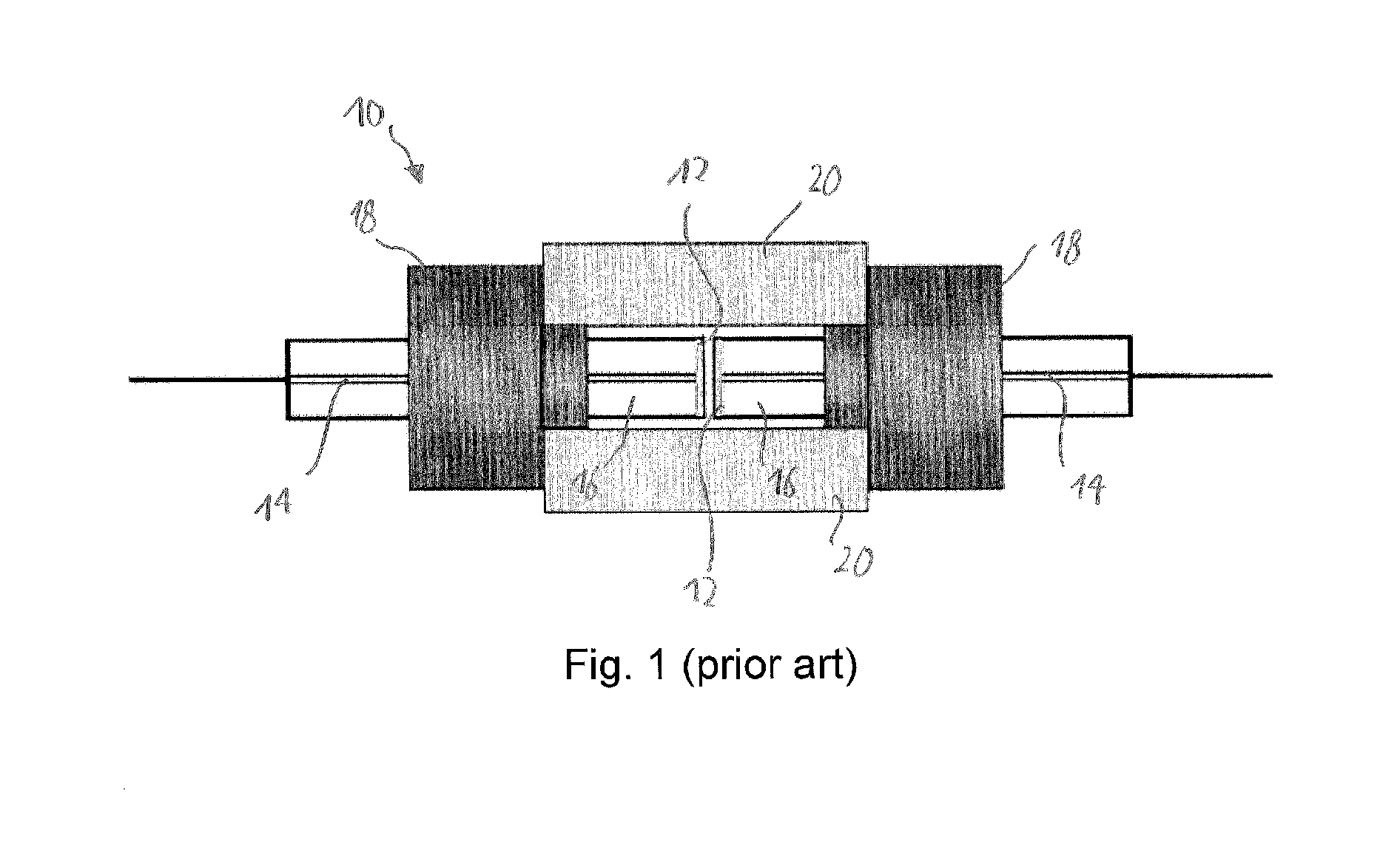
[0158]As is best seen in the sectional view of FIG. 6(a), the FP-TF device 28 of the first embodiment is comprised of two parts, a first part 30 and a second part 32. The second part 32 is very similar to one half of an ordinary fiber FP-TF as shown in FIG. 1 and shall therefore be described first. The second part 32 comprises a second holding frame 34 which may be made from aluminum. The second holding frame 34 supports a ferrule 36 which in turn supports a second optical fiber 38. A second reflective surface 40 is provided at the end of the second optical fiber 38 which is best seen in the enlarged view of FIG. 6(b). As is seen in FIG. 6(b), th...

second embodiment

[0172]FIG. 11 shows the frequency response of the fiber FP-TF device 66 according to the invention, confirming that the response is higher than the DC-response at frequencies considerably above 200 kHz.

[0173]An important constructional difference between the fiber FP-TF device 66 of FIGS. 10(a) and (b) as compared to the embodiments of FIGS. 1 and 2 is again that the first piezo-actuator 74 only drives the first reflecting element, i.e. the reflecting surface at the end of the fiber held by the first ferrule 68, so that the mass that needs to be moved by the first piezo-actuator 74 is comparatively small. In order to reduce weight, the conical supporting member 76 is made from a light weight metal, such as aluminum or magnesium. Also, the conical shape allows for a large area to receive thrust force from the first piezo-actuator 74 while avoiding unnecessary mass.

[0174]Further, both the first piezo-actuator 74 and the conical supporting member 76 are ring-shaped, allowing the first ...


PUM


Abstract

A Fabry-Pérot tuneable filter device is described with reflecting elements separated by an optical path length to form an optical resonator cavity. A first actuator means is directly or indirectly coupled with a first reflecting element. And the first actuator means is configured to modulate the optical path length between first and second reflecting elements by a modulation amplitude to thereby sweep the optical resonator cavity through a band of optical resonance frequencies with a sweep frequency of 70 kHz or more. And the mechanical coupling between selected elements of the arrangement is sufficiently low such that when operated at the sweep frequency, the selected elements act as a system of coupled oscillating elements. In addition or alternatively, the first actuator means is directly or indirectly coupled with the first reflecting element so as to substantially drive the first reflecting element only.

Description

FIELD OF THE INVENTION[0001]The present invention is in the field of optics. In particular, the present invention relates to a Fabry-Pérot tuneable filter (FP-TF) device that allows dynamical tuning in fast frequency sweeps. Such dynamical Fabry-Pérot tuneable filter devices are particularly useful for optical coherence tomography (OCT) applications.BACKGROUND OF THE INVENTION[0002]Optical coherence tomography (OCT) is an optical signal acquisition and processing method. It captures micrometer resolution 3D-images within optically scattering media, such as biological tissue. A distance from a scattering medium is measured by use of interferometric signals. In OCT, comparatively long wavelength light, typically in the near-infrared region is used. This has the advantage that the light may penetrate rather deeply into the scattering medium, allowing to obtain sub-surface images at near-microscopic resolution. OCT has proven particularly useful in the imaging of the human eye, allowing...

Claims


Application Information

Patent Timeline
IPC IPC(8): H01S5/06G01J3/45
CPCG01J3/26G02B6/29358H01S5/141H01S5/423H01S5/02284H01S5/183G02B26/001H01S3/105H01S5/02251
Inventor HUBER, ROBERTWIESER, WOLFGANGKLEIN, THOMASEIGENWILLIG, CHRISTOPHBIEDERMANN, BENJAMINMUELLNER, DIETEREDER, MICHAEL
Owner LUDWIG MAXIMILIANS UNIV MUNCHEN
Why Eureka
Try Eureka