Electrostatic Vascular Filters

a filter and electrostatic technology, applied in the field of medical devices, can solve the problems of fat embolism syndrome, particularly harmful ffas in the circulation, and large escaped fat particle load,

Inactive Publication Date: 2013-03-21
SCHNEIDER M BRET +1
View PDF14 Cites 30 Cited by
  • Summary
  • Abstract
  • Description
  • Claims
  • Application Information

AI Technical Summary

Benefits of technology

This patent describes a filter system that can remove harmful particles from a person's blood vessels. The filter is made of a conductive material that attracts particles with an opposite electrostatic charge. It can be placed in the blood vessels using a minimally invasive procedure and can capture particles as small as 10 microns. The invention has the technical effects of reducing the risk of stroke and other complications related to blood vessel obstruction.

Problems solved by technology

FFAs are particularly harmful in the circulation.
The embolization of fat particles into organs including the lung and brain is an important cause of medical morbidity, particularly following orthopedic trauma.
Following orthopedic surgical procedures, however, the escaped fat particle load becomes very large, and a fat embolism syndrome may occur in a third of patients undergoing these procedures.
Particles of these materials, however, are frequently taken away from the operative site by nearby veins.
When the particles are brought into the fine capillaries of the lung or other regions of the body, circulatory blockages and tissue damage may result.
The engineering of vascular filters is complicated by the need to make the particle-capturing mesh tight enough to capture the targeted particles, but not so tight so as to impede circulation, or otherwise cause thrombus formation on the mesh.
An excessively loose mesh (in which the spaces between the filter elements are too distant) results in failure to capture smaller emboli.
Conversely, a mesh that is too tight (in which filter elements are too close to one another) increases the resistance to blood flow, and may trap particles indiscriminately, leading to early thrombosis and occlusion of paths through the filter.
Electrostatic filters are known principally for use in water filtration, cleaning of fabric, air / allergen filtration, and in food processing, but have not been adapted to the unique environment and demands of intravascular use.

Method used


Image

  • Electrostatic Vascular Filters
  • Electrostatic Vascular Filters
  • Electrostatic Vascular Filters

Examples


Embodiment Construction

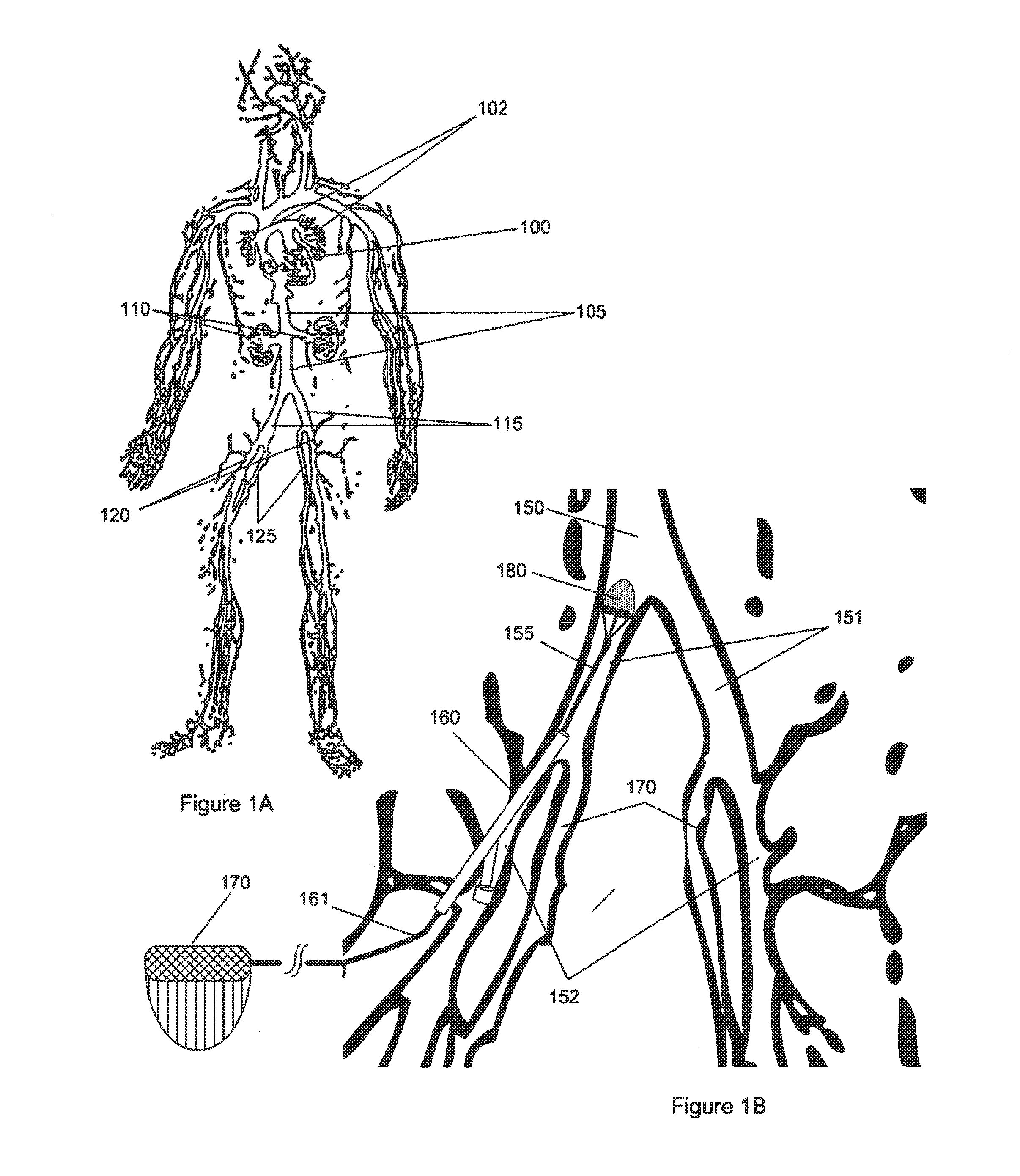
[0048]FIG. 1A illustrates the major anatomical aspects of the human venous system. Via this natural system, deoxygenated blood is returned to heart 100 via inferior vena cava 105, and oxygenated blood via pulmonary veins 102. Below renal veins 110, inferior vena cava 105 emerges from the convergence of the left and right common iliac veins 115. Femoral veins 120 emerge upstream (distally) from the common iliac veins 115, and long saphenous veins 125 also arise in this region.

[0049]As shown in FIG. 1B, each of the common iliac veins 151 arises from the confluence of the femoral veins 152 and the long saphenous veins 170. Interventional catheter 155 may be placed into this system through femoral vein 152, for example through the lumen of guide catheter 160 which may contain electrically conductive wires 161. Through the lumen, catheter 155 may advance to, for example, the common iliac artery, and may deploy filter mechanism 180. Distal end of catheter 155 may be used to deploy and to ...


PUM


Abstract

An intravascular filter is constructed to electrostatically capture and retain particles of a targeted type (for example fat or methacrylate emboli), even if those particles are physically small enough to slip through the filter in the absence of electrostatic attraction. Specific types of targeted particles are thereby captured and retained with improved efficiency, while permitting free flow of non-targeted particles. This improvement permits intravascular filters to be constructed with low-resistance, widely spaced filter elements. Accordingly, more targeted particles are captured, less thrombosis occurs, less pressure drop occurs across the filter, and perfusion or blood collection in downstream areas is maintained.

Description

CROSS-REFERENCES TO RELATED APPLICATIONS[0001]The present application is a Divisional of U.S. Pat. No. 12 / 383,094 filed Mar. 18, 2009 (Allowed), which application claims the benefit of priority of U.S. Provisional Appln. No. 61 / 037,983 filed Mar. 19, 2008. The full disclosures, each of which are incorporated herein by reference in their entirety for all purposes.FIELD OF THE INVENTION[0002]The invention described herein relates to medical devices and methods of use thereof. More particularly, the invention relates to a retrievable intravascular filter and methods for filtering embolic material within a vessel of a subject.REFERENCES[0003]Berger, US Patent Application Publication No. US2007 / 0225644 A1, Embolic Removal for Orthopedic Procedures, Sep. 27, 2007.[0004]Clubb et al., U.S. Pat. No. 7,220,271 82, Embolic Filters Having Multiple Layers and Controlled Pore Size.[0005]McGuckin et al., U.S. Pat. No. 6,623,506, Vein Filter.[0006]Sutton, U.S. Pat. No. 7,229,462, Vascular Filter Sy...

Claims


Application Information

Patent Timeline
Patent Type & Authority Applications(United States)
IPC IPC(8): A61F2/01
CPCA61F2230/008A61F2230/0093A61F2/013A61F2230/0006A61F2/01A61F2002/018A61F2250/0001A61F2/0105A61F2/0108
Inventor SCHNEIDER, M. BRETMONCADA, ROGELIO
Owner SCHNEIDER M BRET
Why Eureka
Try Eureka