Waste heat recovery system

a heat recovery system and waste heat technology, applied in the direction of mechanical equipment, machines/engines, non-fuel substance addition to fuel, etc., can solve the problems of not obtaining the required engine output, the nitrogen oxides in the exhaust gas cannot be efficiently reduced, and the recirculation exhaust gas or the compressed air cannot be sufficiently cooled in the exhaust gas boiler or the compressed air boiler, etc., to achieve the effect of reducing evaporation pressure and reducing evaporation pressur

Inactive Publication Date: 2013-03-28
TOYOTA IND CORP
View PDF5 Cites 36 Cited by
  • Summary
  • Abstract
  • Description
  • Claims
  • Application Information

AI Technical Summary

Benefits of technology

[0008]In accordance with an aspect of the present invention, a waste heat recovery system is for use with a power unit that includes an internal combustion engine. The waste heat recovery system includes a Rankine cycle device in which working fluid circulates through a pump, a boiler, an expander and then through a condenser, heat exchange occurs in the boiler between the working fluid and intake fluid that is introduced into the internal combustion engine while being cooled, a determination device for determining required cooling load for the intake fluid, a pressure reducing device for reducing evaporation pressure in the Rankine cycle device, and a controller for controlling the pressure reducing device so as to reduce the evaporation pressure below a predetermined evaporation pressure if the required cooling load determined by the determination device exceeds a threshold.

Problems solved by technology

If the temperature of recirculation exhaust gas exiting the exhaust gas boiler or the temperature of compressed air exiting the compressed air boiler exceeds a predetermined threshold and the required cooling load for such recirculation exhaust gas or compressed air is large, the recirculation exhaust gas or the compressed air cannot be sufficiently cooled in the exhaust gas boiler or in the compressed air boiler.
Thus, there is a fear that the required engine output cannot be obtained due to such insufficient cooling of compressed air and also that nitrogen oxides in exhaust gas cannot be efficiently reduced due to such insufficient cooling of recirculation exhaust gas.

Method used


Image

  • Waste heat recovery system
  • Waste heat recovery system
  • Waste heat recovery system

Examples


first embodiment

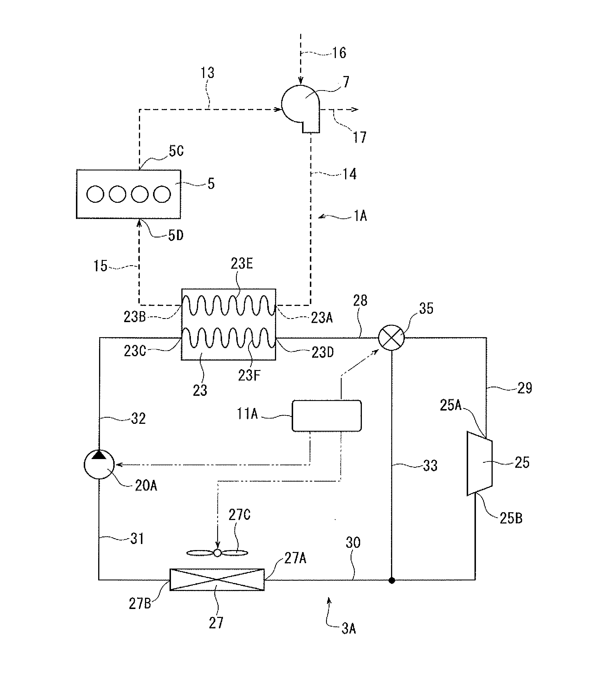
[0024]Referring to FIG. 1, the waste heat recovery system of the first embodiment is installed in a vehicle and used with a power unit 1A of the vehicle. The waste heat recovery system includes a Rankine cycle device 3A, a bypass passage 33, a regulator valve 35 and a controller 11A. The bypass passage 33 and the regulator valve 35 correspond to the pressure reducing device of the present invention. The controller 11A corresponds to the determination device of the present invention.

[0025]The power unit 1A has an internal combustion engine 5 and a turbocharger 7 as a forced-induction compressor. The engine 5 is a conventional water-cooled gasoline engine having a water jacket (not shown) through which coolant flows. The engine 5 has an outlet 5C for discharging exhaust gas and an inlet 5D for introducing compressed air.

[0026]The turbocharger 7 is of a widely used type. The turbocharger 7 is driven by the exhaust gas exiting the engine 5 to compress the intake air. Compressed air is s...

second embodiment

[0051]In the system of the second embodiment, if the controller 11A determines that the required cooling load for compressed air exceeds a predetermined threshold, the controller 11A cooperates with the electric motor M to decrease the speed of the pump 20B so that the flow rate of working fluid discharged from the pump 20B decreases. By doing so, the flow rate of the working fluid discharged from the pump 20B becomes relatively lower than that of the working fluid flowing into the expander 25, thereby reducing the evaporation pressure of the Rankine cycle device 3A.

[0052]Thus, the second embodiment also provides the advantages similar to those of the first embodiment.

[0053]FIG. 5 shows the third embodiment of the waste heat recovery system. The third embodiment differs from the second embodiment in that a variable displacement pump 20C controlled by the controller 11A is used instead of the pump 20B of the second embodiment. The controller 11A and the pump 20C corresponds to the pr...

third embodiment

[0054]In the system of the third embodiment, if the controller 11A determines that the required cooling load for compressed air exceeds a predetermined threshold, the controller 11A causes the pump 20C to be operated so as to decrease its displacement, that is, to decrease the amount of fluid pumped per revolution of the pump 20C so that the flow rate of working fluid discharged from the pump 20C decreases. By doing so, the flow rate of the working fluid discharged from the pump 20C becomes relatively lower than that of the working fluid flowing into the expander 25, thereby reducing the evaporation pressure of the Rankine cycle device 3A.

[0055]Thus, the third embodiment also provides the advantages similar to those of the first embodiment.

[0056]FIG. 6 shows the fourth embodiment of the waste heat recovery system. The waste heat recovery system of the fourth embodiment is also installed in a vehicle and used with a power unit 1B of the vehicle. The waste heat recovery system include...


PUM


Abstract

A waste heat recovery system is for use with a power unit that includes an internal combustion engine. The waste heat recovery system includes a Rankine cycle device in which working fluid circulates through a pump, a boiler, an expander and then through a condenser, heat exchange occurs in the boiler between the working fluid and intake fluid that is introduced into the internal combustion engine while being cooled, a determination device for determining required cooling load for the intake fluid, a pressure reducing device for reducing evaporation pressure in the Rankine cycle device, and a controller for controlling the pressure reducing device so as to reduce the evaporation pressure below a predetermined evaporation pressure if the required cooling load determined by the determination device exceeds a threshold.

Description

BACKGROUND OF THE INVENTION[0001]The present invention relates to a waste heat recovery system.[0002]Japanese Unexamined Patent Application Publication No. 2007-239513 discloses a waste heat recovery system used with a power unit and having a Rankine cycle device in which working fluid circulates. The power unit has an internal combustion engine and an exhaust gas recirculation passage through which part of the exhaust gas exiting the engine is recirculated into the engine as recirculation exhaust gas. The Rankine cycle device has a pump, an exhaust gas boiler, an expander, a condenser and a tube. In the exhaust gas boiler, the working fluid is heated by heat exchange with recirculation exhaust gas. Working fluid is circulated through the pump, the exhaust gas boiler, the expander and then the condenser which are connected by the tube.[0003]Japanese Unexamined Patent Application Publication No. 2008-8224 discloses another waste heat recovery system used with a power unit and having ...

Claims


Application Information

Patent Timeline
Patent Type & Authority Applications(United States)
IPC IPC(8): F02G5/02F02M25/07F02B37/00F01K23/10
CPCF01K23/10F02G5/02F01N5/02F02B29/0493Y02T10/16Y02T10/121F01K23/065F02B29/0443F02M25/0731F02M25/0754Y02T10/146Y02T10/166F02M26/28F02M26/47Y02T10/12
Inventor MORI, HIDEFUMIIGUCHI, MASAOENOKIJIMA, FUMINOBUISHIGURO, FUMIHIKO
Owner TOYOTA IND CORP
Why Eureka
Try Eureka