Piston ring for engine and manufacturing method thereof

Inactive Publication Date: 2013-03-28
HYUNDAI MOTOR CO LTD
View PDF4 Cites 10 Cited by
  • Summary
  • Abstract
  • Description
  • Claims
  • Application Information

AI Technical Summary

Benefits of technology

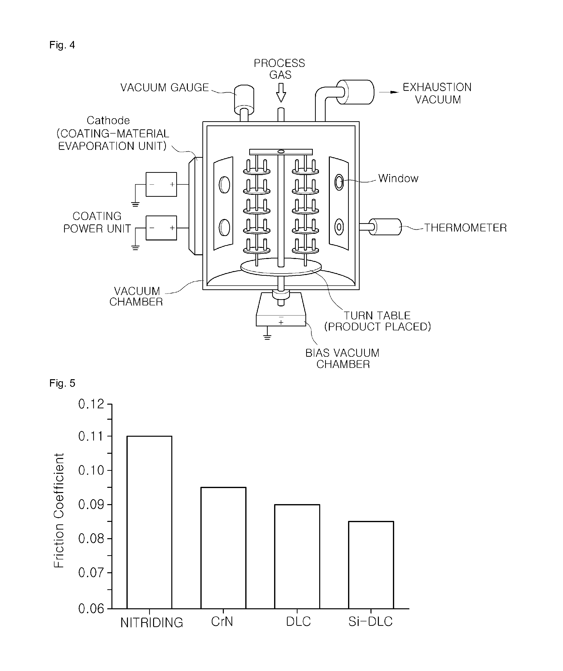
[0017]As apparent from the above description, the present invention provides a piston ring for an engine and a manufacturing method thereof, in which the frictional coefficient of Si-DLC is less than Cr plating and nitriding by at

Problems solved by technology

Such a piston ring has difficulties in maintaining durability as well as having a low frictional coefficient.
However, the DLC is problematic in that friction and durability are deteriorated when t

Method used


Image

  • Piston ring for engine and manufacturing method thereof
  • Piston ring for engine and manufacturing method thereof
  • Piston ring for engine and manufacturing method thereof

Examples


Embodiment Construction

[0026]Hereinafter reference will now be made in detail to various embodiments of the present invention, examples of which are illustrated in the accompanying drawings and described below. While the invention will be described in conjunction with exemplary embodiments, it will be understood that the present description is not intended to limit the invention to those exemplary embodiments. On the contrary, the invention is intended to cover not only the exemplary embodiments, but also various alternatives, modifications, equivalents and other embodiments, which may be included within the spirit and scope of the invention as defined by the appended claims.

[0027]It is understood that the term “vehicle” or “vehicular” or other similar term as used herein is inclusive of motor vehicles in general such as passenger automobiles including sports utility vehicles (SUV), buses, trucks, various commercial vehicles, watercraft including a variety of boats and ships, aircraft, and the like, and i...


PUM

PropertyMeasurementUnit
Thicknessaaaaaaaaaa
Circumferenceaaaaaaaaaa
Contentaaaaaaaaaa

Abstract

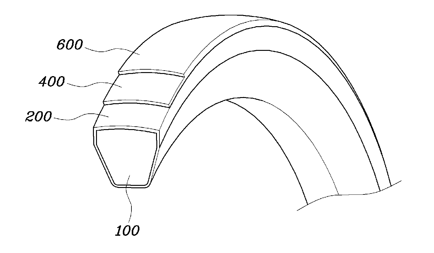
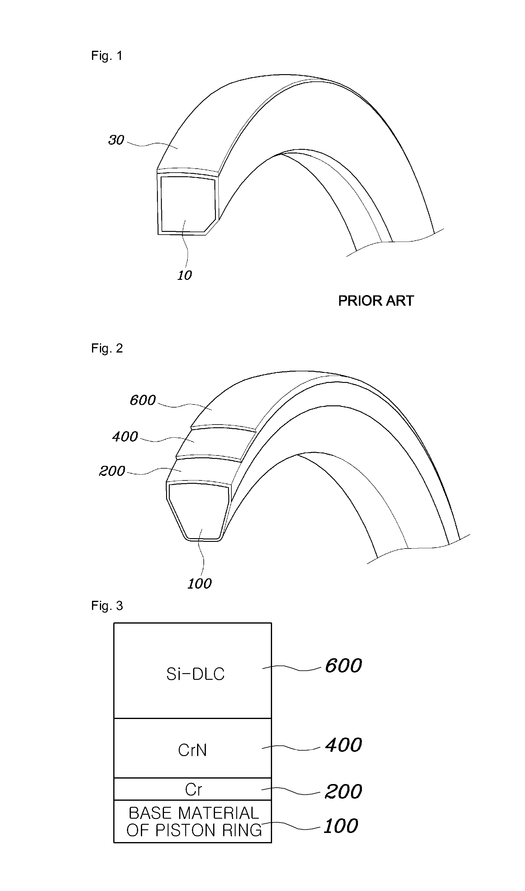
Disclosed is a piston ring for an engine and a method of manufacturing the piston ring. The piston ring includes at least a Cr (Chromium) coating layer coated on a surface of a base material, and a Si-DLC (Silicon doped Diamond Like Carbon) coating layer coated on an outermost layer above the Cr layer and the base material. More specifically, the Si-DLC layer includes about 3 to 10 wt. % of Si.

Description

CROSS-REFERENCE TO RELATED APPLICATION[0001]This application claims under 35 U.S.C. §119(a) the benefit of Korean Patent Application No. 10-2011-0097315 filed on Sep. 27, 2011, the entire contents of which are incorporated herein by reference.BACKGROUND[0002](a) Technical Field[0003]The present disclosure relates to a piston ring for an engine configured so that an outer circumference of the piston ring is treated with low friction Si-DLC (Silicon doped Diamond Like Carbon) to reduce friction loss in an engine cylinder and to improve fuel efficiency, and a method of manufacturing the piston ring thereof.[0004](b) Background Art[0005]A piston ring is defined as one pair of rings that are fitted into grooves of an outer circumference of a piston to maintain a certain degree of air-tightness between the piston and an inner wall of a cylinder and scrape a lubricant off the wall of the cylinder, thus preventing the lubricant from flowing into a combustion chamber.[0006]FIG. 1 shows a coa...

Claims


Application Information

Patent Timeline
IPC IPC(8): F16J9/00C23C16/44C23C16/27
CPCF16J9/26C23C14/0641C23C14/16C23C28/322C23C14/34C23C28/34C23C28/343C23C14/228F02F5/00F16J9/12F16J9/20
Inventor AN, JEONG UK
Owner HYUNDAI MOTOR CO LTD
Why Eureka
Try Eureka