

Optical element and method for manufacturing the same
a technology of optical elements and manufacturing methods, applied in the field of optical elements, can solve the problems of generating flares, unable to sufficiently correct chromatic aberration in some cases, etc., and achieve the effect of suppressing the change in properties (light resistance, aging resistance)
- Summary
- Abstract
- Description
- Claims
- Application Information
AI Technical Summary
Benefits of technology
Problems solved by technology
Method used
Image

Examples
first embodiment
[0030]In a method for manufacturing an optical element according to a first embodiment, after a first material including a precursor of a first energy curable resin which contains fine particles of a transparent conductive material is provided on a transparent substrate and is then cured by light irradiation, a heat treatment is performed, and furthermore, the cured first material processed by the heat treatment is again processed by light irradiation (hereinafter referred to as “post light irradiation” in some cases). An optical element obtained by the manufacturing method according to aspects of the present invention which uses a material containing a transparent conductive material dispersed therein can suppress the change in the refractive index / transmission at a long wavelength caused by light, such as ultraviolet light.
[0031]In addition, the method for manufacturing an optical element according to the first embodiment includes the following two methods for manufacturing a mult...
second embodiment
[0075]An optical element according to a second embodiment is an optical element having a first member containing fine particles of a transparent conductive material and a second transparent substrate in this order on a first transparent substrate, and the first member is provided with a layer which inhibits permeation of oxygen at a portion in contact with the air and which has an oxygen permeability of 2.0×10⁻¹¹ P / cm3·cm·(cm2·s·cmHg)−1 or less measured by a high-vacuum pressure difference method. With reference to FIG. 10, the optical element of the second embodiment will be described. In FIG. 10, a first member 22 containing fine particles of a transparent conductive material and a second transparent member 23 are provided on a first transparent member 21. The first member 22 containing fine particles of a transparent conductive material is provided with a layer 24 which inhibits permeation of oxygen so as not to be in contact with the air.
[0076]The optical element of the second e...
example 1
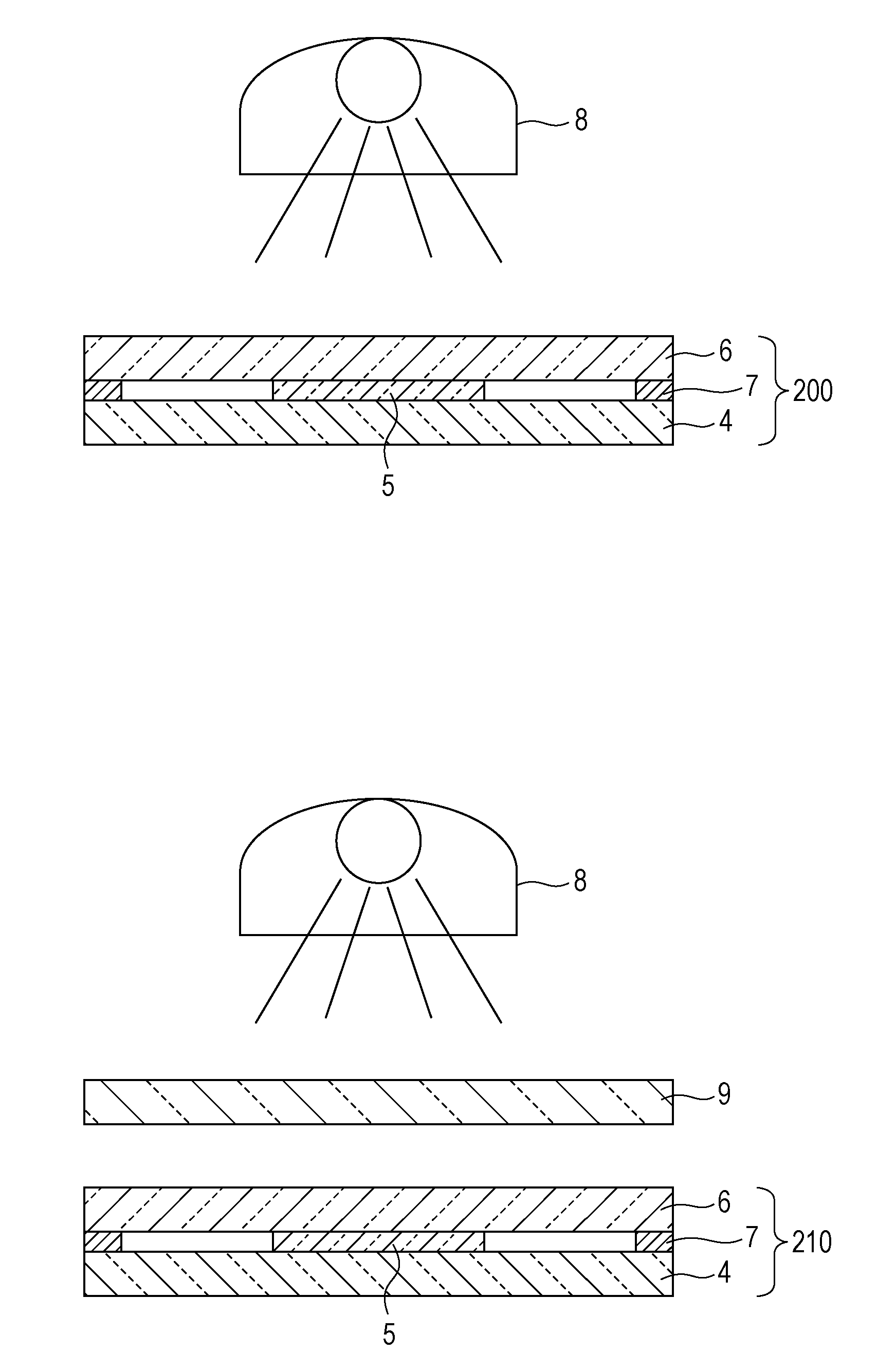
200 for Refractive Index Measurement>
[0099]An optical element 200 for refractive index measurement was formed as described below.
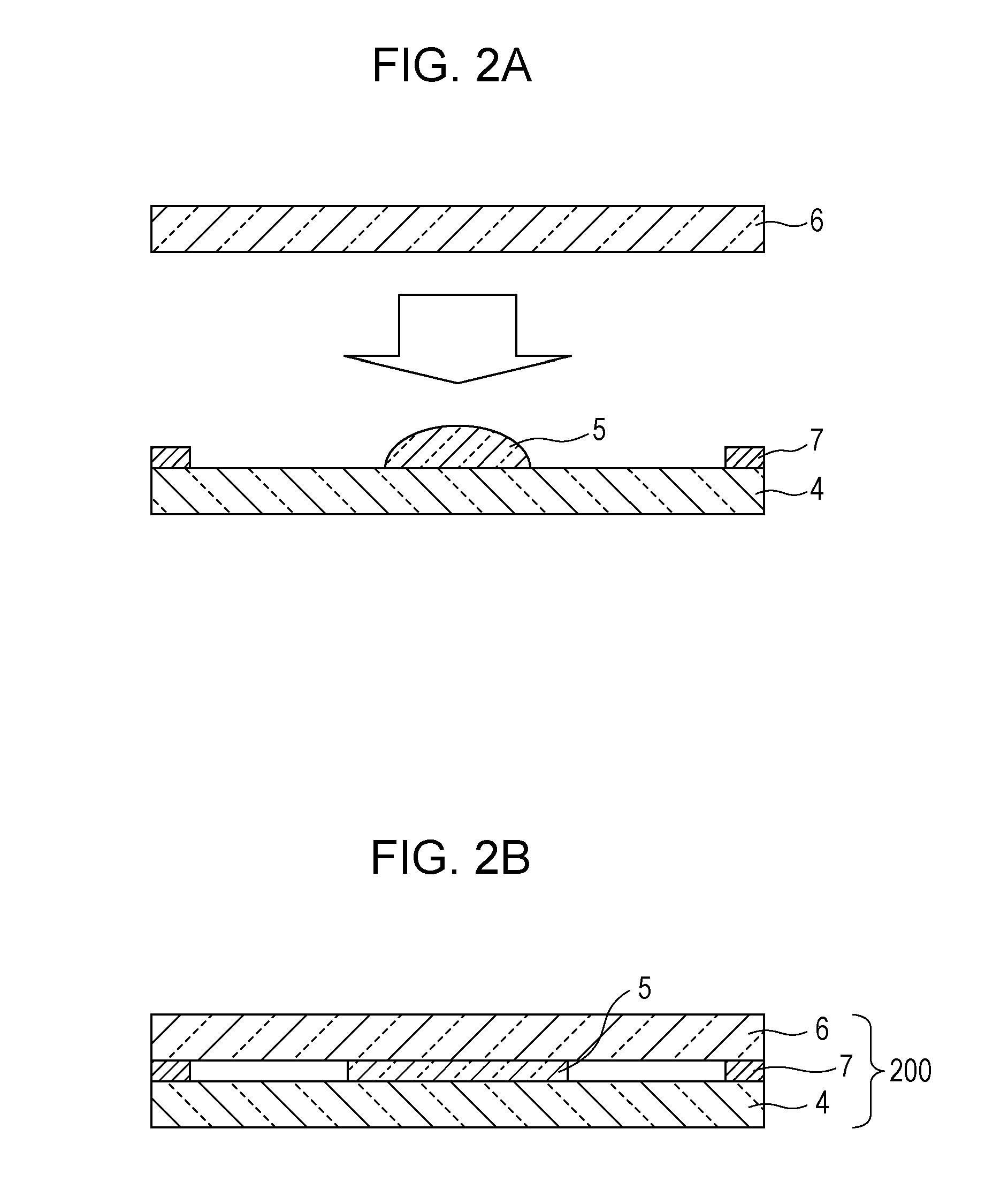
[0100]First, as shown in FIG. 2A, a spacer 7 having a thickness of 12.5 μm and an ITO fine-particle dispersion material 5 (low refractive index and high dispersion material 11) were arranged on a high refractive index glass (S-TIH11: manufactured by Hoya Corp.) 4 having a thickness of 1 mm. In addition, a quartz glass 6 having a thickness of 1 mm was placed on the ITO fine-particle dispersion material 5 with the spacer 7 provided therebetween so as to extend the ITO fine-particle dispersion material 5 by pressure application. The structure thus formed was irradiated by a high pressure mercury lamp (UL750, manufactured by Hoya Candeo Optronics Corp.) at 20 mW / cm2 (illuminance through the quartz glass, illuminance meter: UIT-250, light receiving portion: UVD-S365) for 1,300 seconds (26 J), so that a measurement sample was cured. After the curing was performe...
PUM
| Property | Measurement | Unit |
|---|---|---|
| Fraction | aaaaa | aaaaa |
| Fraction | aaaaa | aaaaa |
| Percent by volume | aaaaa | aaaaa |
Abstract
Description
Claims
Application Information