
Data transmission and reception method and apparatus robust against phase noise for high efficiency satellite transmission

a data transmission and reception method technology, applied in the field of satellite transmission systems, can solve the problems of increasing the computational complexity at the reception end, the data is not properly restored, etc., and achieve the effect of high efficiency

Inactive Publication Date: 2013-03-28
ELECTRONICS & TELECOMM RES INST
View PDF9 Cites 25 Cited by
  • Summary
  • Abstract
  • Description
  • Claims
  • Application Information

AI Technical Summary

Benefits of technology

The present invention provides a data transmission and reception apparatus and method that can efficiently transmit data over a satellite network. It uses initial phase information calculated from a preamble and postamble of a data packet, as well as a pilot symbol, to calculate a symbol transition of the data packet. This allows for a more robust and accurate transmission of data over the satellite network, despite the presence of phase noise. The technical effect of this invention is to improve the efficiency and reliability of satellite transmission and access systems.

Problems solved by technology

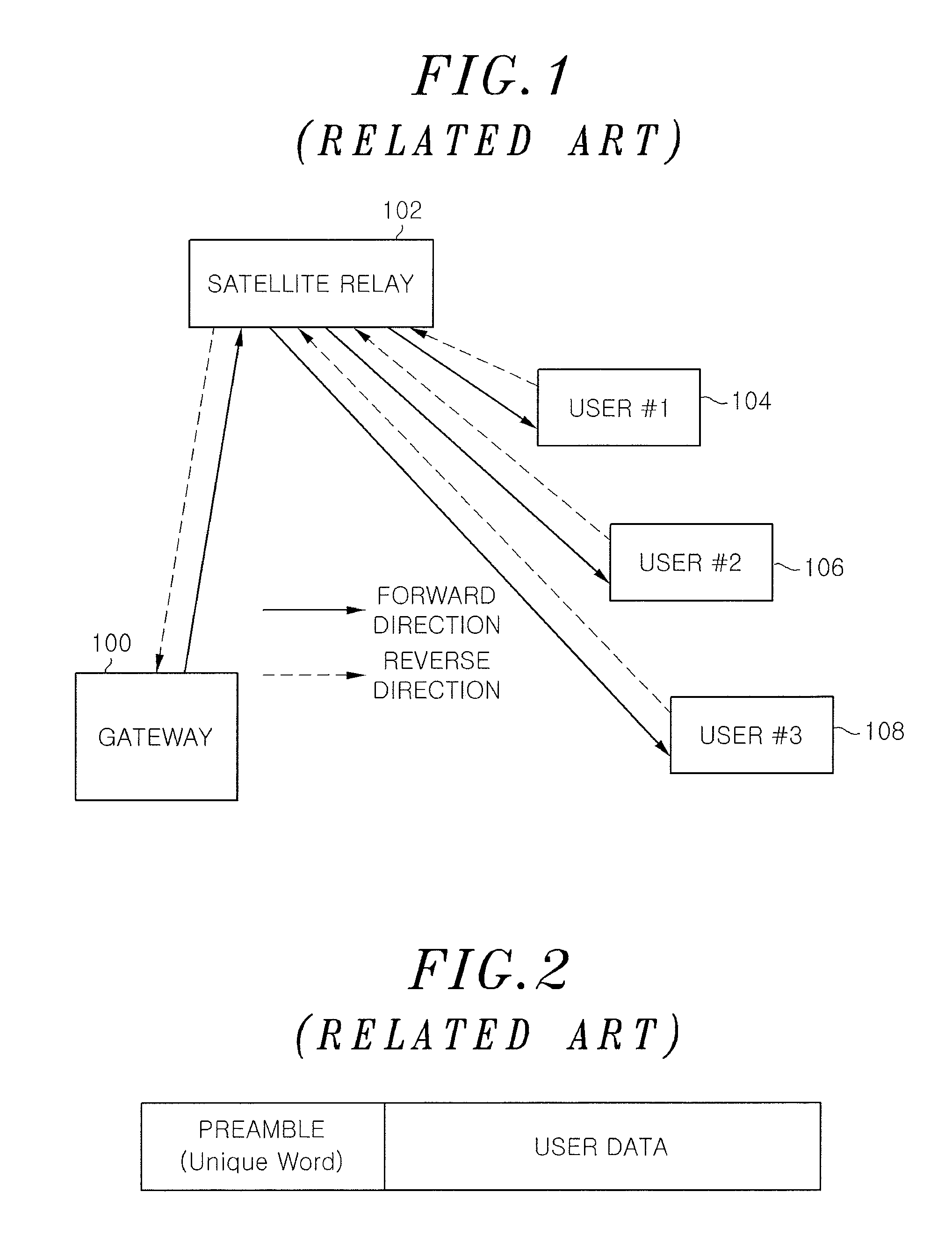
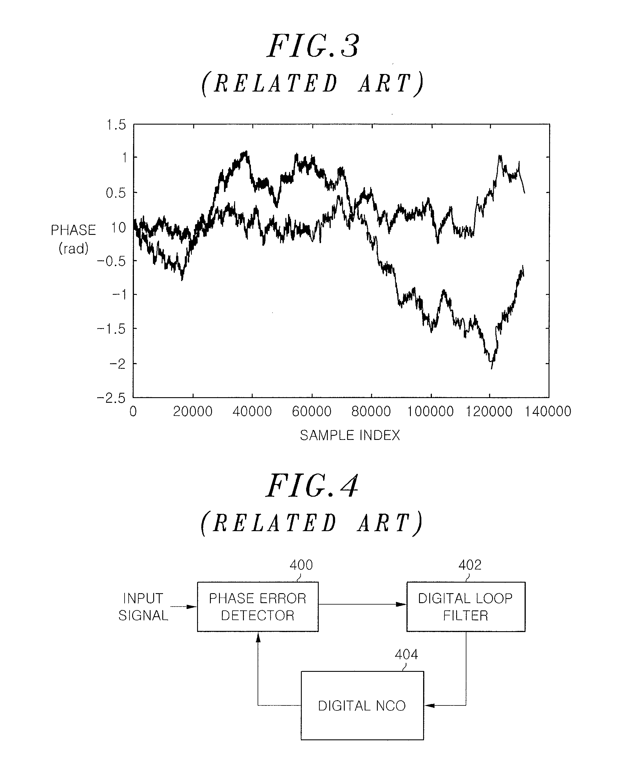
However, as shown in FIG. 3, in the occurrence of a channel error having an irregular random variable such as time variable carrier phase noise, when the channel error is estimated in the preamble and subsequently compensated for in a data section, an estimate error occurs, which causes a problem that data is not properly restored.
In addition, in order to address this problem, carrier phase noise is obtained at a reception end with respect to all possible data streams and then data is restored using the same, which entails an increase of computational complexity at the reception end.

Method used


Image

  • Data transmission and reception method and apparatus robust against phase noise for high efficiency satellite transmission
  • Data transmission and reception method and apparatus robust against phase noise for high efficiency satellite transmission
  • Data transmission and reception method and apparatus robust against phase noise for high efficiency satellite transmission

Examples


Embodiment Construction

[0024]Hereinafter, embodiments of the present invention will be described in detail with the accompanying drawings.

[0025]In a satellite broadcast / communication system, a signal transmission and reception model may be expressed by Eq. (1) below:

rk=skejθk+nk,

where k=0, . . . , P−1  Eq. (1)

[0026]In Equation, when a channel carrier phase is considered as k index of a time domain, θk may be considered as a random variable having a uniform distribution of a time variable function (−π, π). Herein, r is a reception signal vector, s is a transmission signal vector, and n is expressed as P number of vectors corresponding to AWGN noise.

[0027]In this case, a phase locked loop (PLL) scheme has been mainly used a method of tracking a change in phase noise.

[0028]FIG. 4 is a block diagram of a PLL for phase synchronization in accordance with the related art.

[0029]In the case of the PLL scheme, compensation for phase noise is performed through a tracking of a phase variation by optimizing a gain va...


PUM


Abstract

A data transmission and reception apparatus is used for a high efficiency satellite transmission. The apparatus includes an initial phase calculation unit to calculate initial phase information using a preamble and a postamble of a data packet applied thereto, a symbol transition calculation unit to perform forward and backward metric operations using the initial phase information calculated by the initial phase calculation unit and a pilot symbol in the data packet to calculate a symbol transition of the data packet, and a phase error estimation unit to calculating a phase error using the pilot symbol in a spot where the pilot symbol is positioned, the calculated phase error being provided to the symbol transition calculation unit.

Description

RELATED APPLICATION(S)[0001]This application claims the benefit of Korean Patent Application Nos. 10-2011-0097857 and 10-2012-0074998, filed on Sep. 27, 2011 and Jul. 10, 2012, respectively, which are hereby incorporated by reference as if fully set forth herein.FIELD OF THE INVENTION[0002]The present invention relates to a satellite transmission system, and more particularly, to a data transmission and reception apparatus and method robust against phase noise for a high efficiency satellite transmission in a time division multiplexing (TDM) / time division multiple access (TDMA) satellite transmission and access system.BACKGROUND OF THE INVENTION[0003]In general, a TDM / TDMA scheme is mainly used as a transport protocol in a conventional broadband satellite broadcast / communication system. In case of a broadcast system, data is transmitted in the form of a continuous stream based on a TDM scheme, and a start point of a frame is detected on a basis of known data (unique data) at a recep...

Claims


Application Information

Patent Timeline
IPC IPC(8): H04B7/212
CPCH04B7/18513
Inventor KIM, PANSOOOH, DEOCK GIL
Owner ELECTRONICS & TELECOMM RES INST
Learn More