Collimator, detector arrangement, and ct system

Inactive Publication Date: 2013-03-28
SIEMENS AG
View PDF5 Cites 12 Cited by
  • Summary
  • Abstract
  • Description
  • Claims
  • Application Information

AI Technical Summary

Benefits of technology

[0026]Example embodiments also provide a computed tomography (CT) system having at least one of the above-described detector arrangements and by which tomographical recordings of an object being examined can be generated. Usin

Problems solved by technology

However, said additional signal contribution results in a poorer signal-to-noise ratio so that disruptive image artifacts may arise if the proportion of scattered radiation changes locally, meaning for respectively adjacent detector elements.
ASCs known to date and employed in CT systems are of one-dimensional design and limit the angular acceptance only in the phi direction.
That edge effect will give rise to annular image art

Method used


Image

  • Collimator, detector arrangement, and ct system
  • Collimator, detector arrangement, and ct system
  • Collimator, detector arrangement, and ct system

Examples


Embodiment Construction

[0033]Various example embodiments will now be described more fully with reference to the accompanying drawings in which only some example embodiments are shown. Specific structural and functional details disclosed herein are merely representative for purposes of describing example embodiments. The present invention, however, may be embodied in many alternate forms and should not be construed as limited to only the example embodiments set forth herein.

[0034]Accordingly, while example embodiments of the invention are capable of various modifications and alternative forms, embodiments thereof are shown by way of example in the drawings and will herein be described in detail. It should be understood, however, that there is no intent to limit example embodiments of the present invention to the particular forms disclosed. On the contrary, example embodiments are to cover all modifications, equivalents, and alternatives falling within the scope of the invention. Like numbers refer to like ...


PUM


Abstract

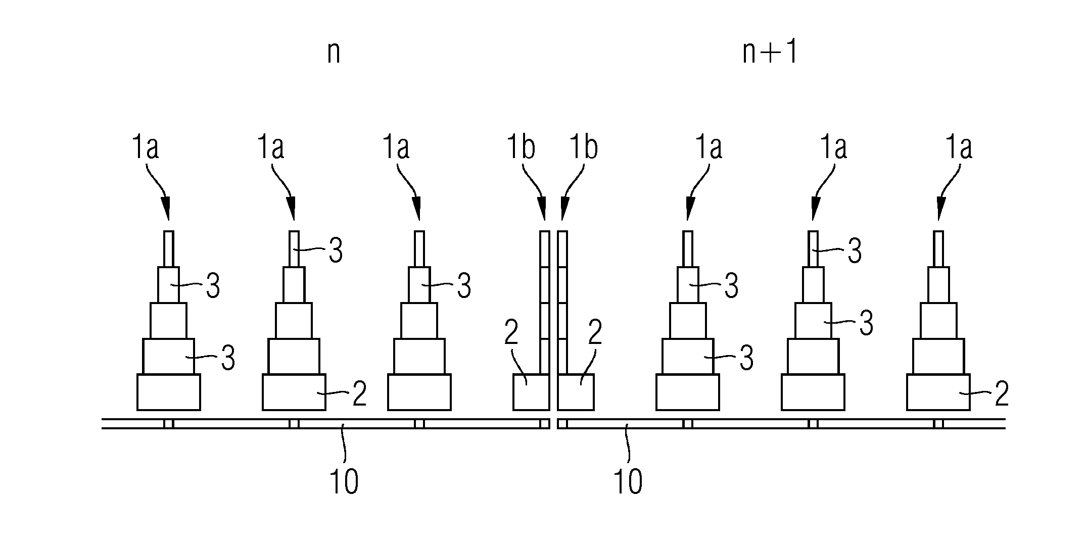
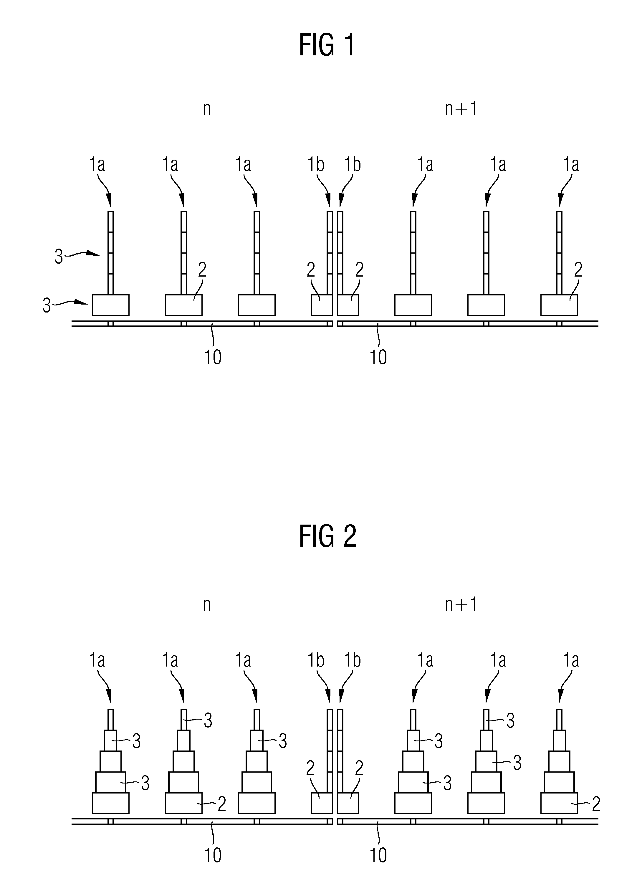
A collimator for a detector, such as an x-ray detector of a CT system, includes a plurality of collimator modules. At least one of the plurality of collimator modules includes at least two outer collimator walls and at least one inner collimator wall (1a). The at least one inner collimator wall (1a) has a plurality of steps.

Description

CROSS-REFERENCE TO RELATED APPLICATION(S)[0001]The present application hereby claims priority under 35 U.S.C. §119 to German patent application number DE 10 2011 083 394.3 filed Sep. 26, 2011, the entire contents of which are hereby incorporated herein by reference.BACKGROUND[0002]1. Field[0003]Example embodiments relate to collimators for detectors, particularly for x-ray detectors of computed tomography (CT) systems, that have a multiplicity of collimator modules, having at least two outer collimator walls and at least one inner collimator wall. Example embodiments further relate to detector arrangements having collimators of such kind and to CT systems having detector arrangements of such kind.[0004]2. Description of Related Art[0005]The relevant information during image reconstruction in CT systems is found in the attenuating of x-rays coming from the x-ray tube's focus. The detector elements of a detector of the CT system that are sensitive to the x-radiation are—without furthe...

Claims


Application Information

Patent Timeline
IPC IPC(8): G21K1/02A61B6/03
CPCA61B6/03G21K1/025A61B6/06
Inventor KREISLER, BJORNREITZ, BODO
Owner SIEMENS AG
Why Eureka
Try Eureka