
Wind energy power plant equipped with an optical vibration sensor

a technology of optical vibration and power plant, which is applied in the direction of optical apparatus testing, non-positive displacement fluid engines, liquid fuel engine components, etc., can solve the problems of high overhead in time and associated cost, lightning damage is a recurring operational problem, and the lighting conductor cannot always adequately protect the sensor equipment, etc., to achieve the effect of reducing the pitch, improving the electricity generation regime, and reducing the pitch of the rotor blad

Active Publication Date: 2013-03-28
VESTAS WIND SYST AS
View PDF3 Cites 19 Cited by
  • Summary
  • Abstract
  • Description
  • Claims
  • Application Information

AI Technical Summary

Benefits of technology

The patent is about a tracking device for wind energy power plants that uses a PIN diode to detect movement of the plant components. The device includes an optical coupler and comparator to compare the sensed movement with a reference interference signal. This allows for small displacements of the surface to be measured with high precision. The device is protected from electrical discharge and can be used on the exterior of the wind energy power plant. Additionally, the patent discusses the use of different materials for the sensor membrane, tailoring its responsiveness to different aerodynamic conditions. The patent also mentions the use of a controller to adjust the rotor blade pitch based on the aerodynamic characteristics of the blade. This helps to optimize the power generation regime.

Problems solved by technology

The dispatch of a service engineer carries a high overhead in terms of time and associated cost, and will only therefore be instructed when a sensor indicates that there is a problem that needs to be rectified.
Due to the height of most wind turbines, damage from lightning strikes is a recurring operational problem.
However, lighting conductors will not always adequately protect sensor equipment, mounted on or in wind turbine components, which by reason of including metallic components such as wiring and circuits, is especially receptive to damage from an electrical discharge.
For example, even if the sensor is not struck by lighting, it may be damaged by induced currents.
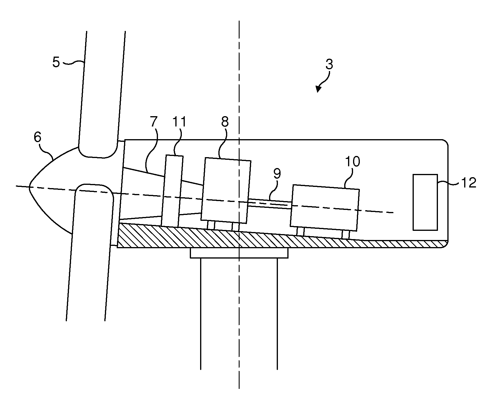
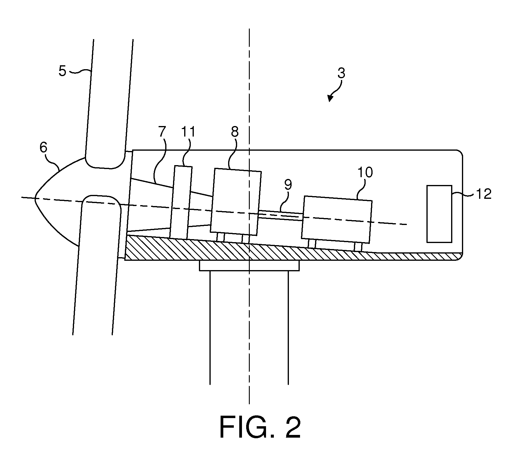
Additionally, within the nacelle, the operation of sensors may be affected by the heavy electrical and mechanical machinery present, such as the generator 10 in particular.
Although sensor damage from such machinery is unlikely, the sensor may not operate in an optimal way.

Method used


Image

  • Wind energy power plant equipped with an optical vibration sensor
  • Wind energy power plant equipped with an optical vibration sensor
  • Wind energy power plant equipped with an optical vibration sensor

Examples


Embodiment Construction

[0040]A wind energy power plant optical vibration sensor will now be described. The sensor has two light sources that emit light at different respective frequencies. The light from the first light source is arranged to fall on a surface of the wind energy power plant at a detection location that is being monitored, such as the surface of a wind turbine blade, or the surface of a component inside the nacelle. Movements in the surface result in changes to the phase of the light reflected back from the surface, and these changes can be detected by mixing the first light with the light emitted from the second light source. The difference in frequencies between the two light sources results in a beating of the resulting interference signal, whereas movements in the sensor surface result in changes in the phase timing and frequency of the beats.

[0041]Reference should now be made to FIG. 3 which illustrates a first example embodiment of the invention. The sensor comprises a first 15 and a ...


PUM


Abstract

A wind energy power plant optical vibration sensor is described, using two light sources 15, 16 that emit light at different respective frequencies. The light from the first light source falls on a surface 44 of the wind energy power plant at a detection site. Movements in the surface result in changes to the phase of the light reflected back from the surface which can be detected by mixing the first light with the light emitted from the second light source. The difference in frequencies between the two light sources results in a beating of the resulting interference signal, whereas movements in the sensor surface result in changes in the phase timing and frequency of the beats.

Description

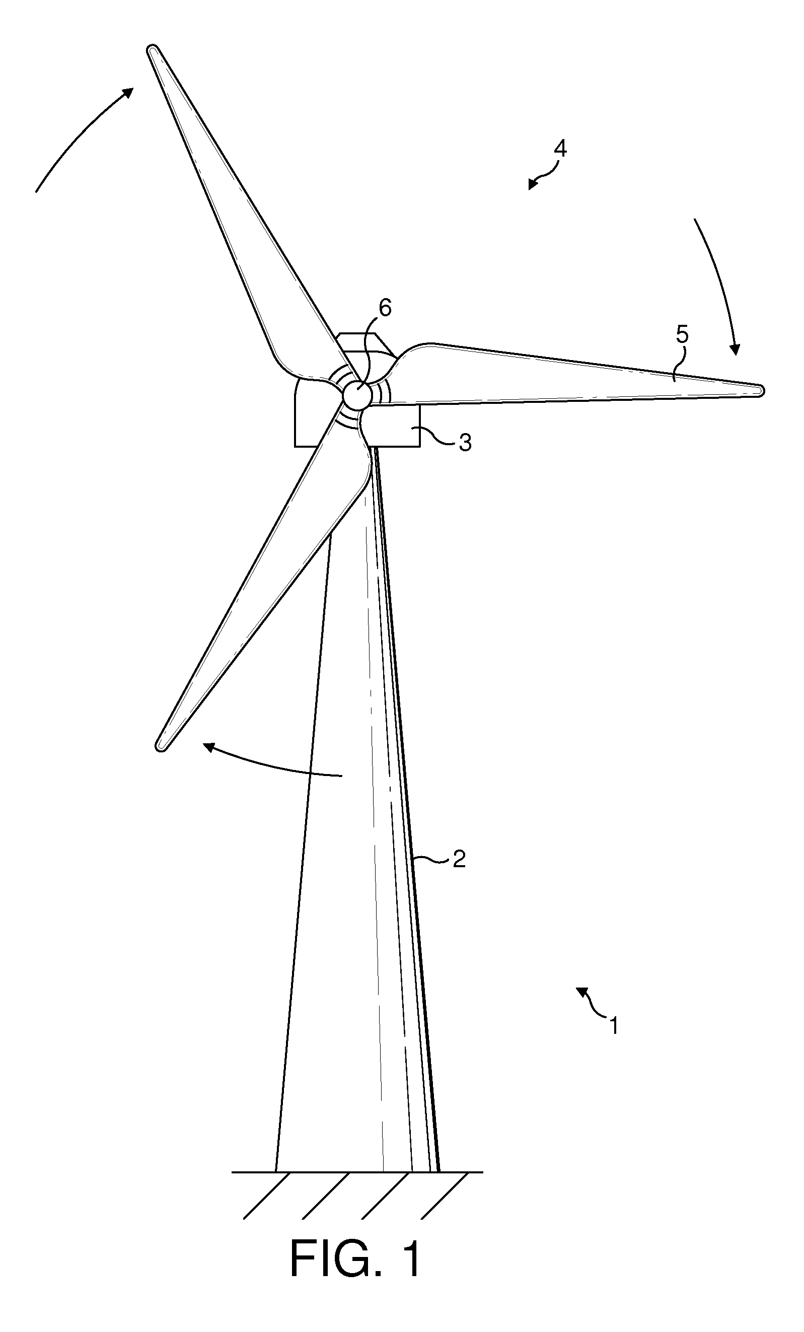
[0001]The present invention relates to a wind energy power plant, and in particular to a wind energy power plant having an optical vibration sensor.[0002]FIG. 1 illustrates a wind energy power plant such as a wind turbine 1. The wind turbine 1 comprises a wind turbine tower 2 on which a wind turbine nacelle 3 is mounted. A wind turbine rotor 4 comprising at least one wind turbine blade 5 is mounted on a hub 6. The hub 6 is connected to the nacelle 3 through a low speed shaft (not shown) extending from the nacelle front. The wind turbine illustrated in FIG. 1 may be a small model intended for domestic or light utility usage, or may be a large model, such as those that are suitable for use in large scale electricity generation on a wind farm for example. In the latter case, the diameter of the rotor could be as large as 100 metres or more.[0003]Wind turbines are typically located in remote areas, such as offshore, coastal, or elevated areas, which offer suitable wind conditions for th...

Claims


Application Information

Patent Timeline
IPC IPC(8): F03D11/00
CPCF03D7/022F03D7/0224F03D7/043F03D11/0091Y02E10/722F05B2270/804G01H9/00Y02E10/723F05B2270/334F03D17/00Y02E10/72F03D80/00G01B9/02015G01D5/266G01D5/28G01H9/006G01M5/0016G01M5/0066G01M9/06G01M11/08G01P13/0013G01P13/0066G01P13/0073G01P13/0086F21V29/70
Inventor OLESEN, IB SVEND
Owner VESTAS WIND SYST AS
Learn More