Geothermal heat exchange system for water supply

a heat exchange system and water supply technology, applied in lighting and heating apparatus, heating fuel, other heat production devices, etc., can solve the problem of pressure head at the plumbing fixture to a practicable level, and achieve the effect of reducing labor and not consuming any other energy

Inactive Publication Date: 2013-04-04
ALRASHIDI THAMER B
View PDF10 Cites 3 Cited by
  • Summary
  • Abstract
  • Description
  • Claims
  • Application Information

AI Technical Summary

Benefits of technology

[0006]The geothermal heat exchange system for a water supply depends entirely upon gravity flow and ambient subsurface temperature for its operation, and does not consume any other energy. The system is particularly well adapted for supplying water to a relatively small facility, such as a washbasin for washing the hands and / or face, etc. The system draws water from an elevated source, e.g., mountaintop or hilltop supply, elevated community water tank or tower, etc., with the water flowing to a subsurface pipe system (one or more pipes) at a lower elevation than the supply. The subsurface pipe system has sufficient length to retain the water flowing therethrough for sufficient time for the water to be heated or cooled to a temperature substantially equal to that at the level of the pipe system below the surface. The pipe or pipes need not be buried to a depth where the subsurface temperature is constant year round, but may be buried at a shallower depth to reduce the labor involved in the installation of the system. The shallower depth still provides most of the heat exchange benefits that would be achieved at a greater depth. The subsurface pipe or pipes are preferably formed of material having a high thermal conductivity for best thermal exchange.

Problems solved by technology

The relatively small diameter pipe or pipes also result in a pressure drop when water is flowing therethrough, thereby reducing the pressure head at the plumbing fixture to a practicable level.

Method used


Image

  • Geothermal heat exchange system for water supply
  • Geothermal heat exchange system for water supply
  • Geothermal heat exchange system for water supply

Examples


Embodiment Construction

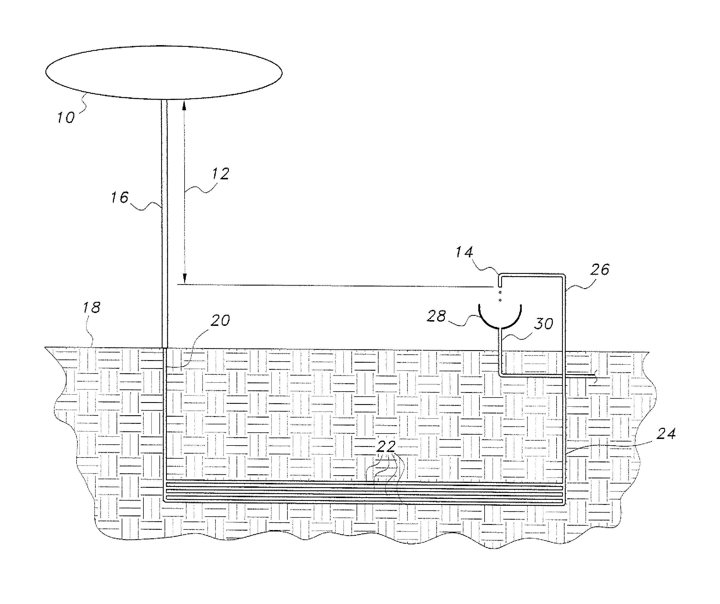
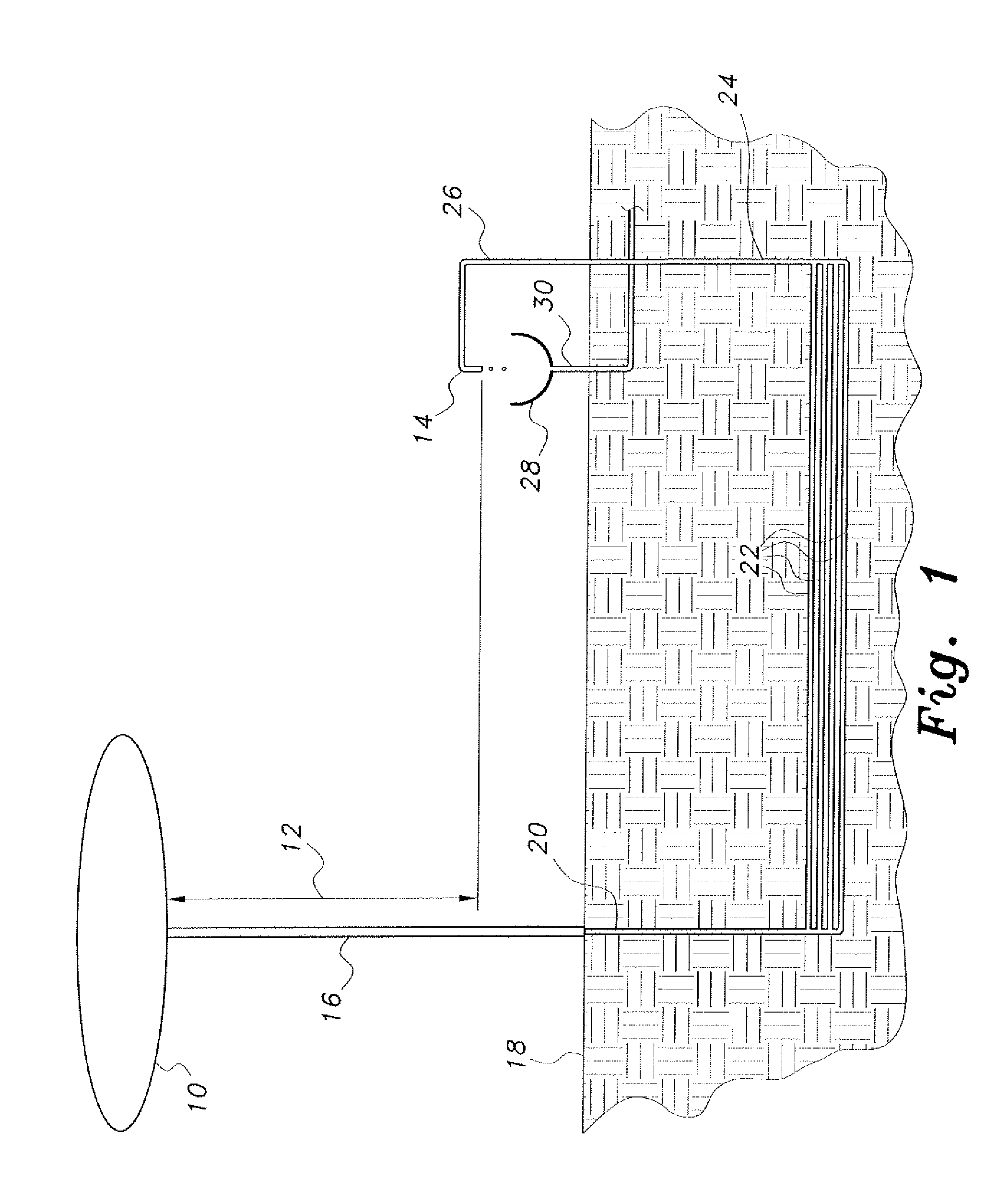
[0013]The geothermal heat exchange system for a water supply is an open-ended water supply system, i.e., water is supplied from an external source to pass through the system, the water being disposed of as wastewater after it is used. The water passes through a subsurface pipe or network of pipes, where the temperature of the water is adjusted substantially to that of the surrounding earth. The system operates entirely by gravity flow from an elevated external source, so that no pumps or power is required for its operation.

[0014]FIG. 1 of the drawings is a schematic illustration of an exemplary geothermal heat exchange system for a water supply according to the present invention. Water is provided from an elevated storage tank or supply 10, e.g., a conventional hilltop or mountaintop water tank, elevated water tower, etc. The water in the tank produces a pressure head 12 relative to the outlet of the system, e.g., a dispensing fixture supply pipe 14, according to the elevation of th...


PUM


Abstract

The geothermal heat exchange system for a water supply is an open system, i.e., water flows into the system for consumption and use and is then drained from the system, as opposed to a closed system where the water is recycled through the system. The present system receives water from an elevated source, e.g., a hilltop tank or an elevated community water supply tank, through a relatively large diameter pipe. The water is then delivered to a subsurface pipe system of one or more relatively small diameter pipes for more efficient thermal exchange. The subsurface pipes are preferably manufactured of material having relatively high thermal conductivity. The subsurface pipe system is preferably buried at an intermediate depth between the surface and the depth where constant temperature occurs in order to provide most of the benefits of a subsurface system while reducing the labor required to bury the pipe system.

Description

BACKGROUND OF THE INVENTION[0001]1. Field of the Invention[0002]The present invention relates generally to systems for the heating and cooling of liquids, and particularly to a geothermal heat exchange system for a water supply.[0003]2. Description of the Related Art[0004]Modern plumbing systems universally provide at least for heated water. Many plumbing systems also provide for the cooling of water from ambient temperature. It is well known that the energy expended for heating and cooling the water supply to a dwelling or other building can be quite costly, depending upon the need for water for the particular structure and its occupants. Water has a relatively high specific heat, i.e., water requires a relatively large amount of energy to heat or cool a given amount by a given temperature difference. In such open-ended systems where the water is used for washing or other consumption and then passes to a drain or other outlet, rather than being recycled, the incoming water must be ...

Claims


Application Information

Patent Timeline
Patent Type & Authority Applications(United States)
IPC IPC(8): F24J3/08
CPCF24J3/082Y02E10/125F24T10/13Y02E10/10
Inventor ALRASHIDI, THAMER B.
Owner ALRASHIDI THAMER B
Why Eureka
Try Eureka