
Light-Emitting Element, Light-Emitting Device, Electronic Device, Lighting Device, and Pyrene-Based Compound

a technology of light-emitting devices and compounds, which is applied in the direction of thermoelectric devices, energy-efficient lighting, sustainable buildings, etc., can solve the problems of reducing external quantum efficiency, difficult to obtain features, and changing chromaticity, so as to reduce external quantum efficiency and reduce the effect of external quantum efficiency and low power consumption

Active Publication Date: 2013-04-11
SEMICON ENERGY LAB CO LTD
View PDF2 Cites 24 Cited by
  • Summary
  • Abstract
  • Description
  • Claims
  • Application Information

AI Technical Summary

Benefits of technology

The present invention provides a highly efficient light-emitting element that can produce multiple emission colors, has a long lifetime, and minimizes a decrease in external quantum efficiency even when a light-emitting layer has a stacked structure. The invention also provides a novel pyrene-based compound suitable for the light-emitting layer of this element. The light-emitting element can produce light of different colors simultaneously using different guest materials and pyrene-based compounds with different HOMO levels. The invention also provides a light-emitting device, electronic device, and lighting device with low power consumption and long lifetime by using the novel pyrene-based compound.

Problems solved by technology

This feature is difficult to obtain with point light sources typified by incandescent lamps and LEDs or linear light sources typified by fluorescent lamps.
However, a light-emitting layer containing plural kinds of light-emitting materials causes problems such as a change in chromaticity and a decrease in external quantum efficiency, due to energy transfer between the light-emitting materials.
However, in that case, a problem is a high possibility of deterioration because of charge accumulation at the interface between the stacked layers, for example.

Method used


Image

  • Light-Emitting Element, Light-Emitting Device, Electronic Device, Lighting Device, and Pyrene-Based Compound
  • Light-Emitting Element, Light-Emitting Device, Electronic Device, Lighting Device, and Pyrene-Based Compound
  • Light-Emitting Element, Light-Emitting Device, Electronic Device, Lighting Device, and Pyrene-Based Compound

Examples


embodiment 1

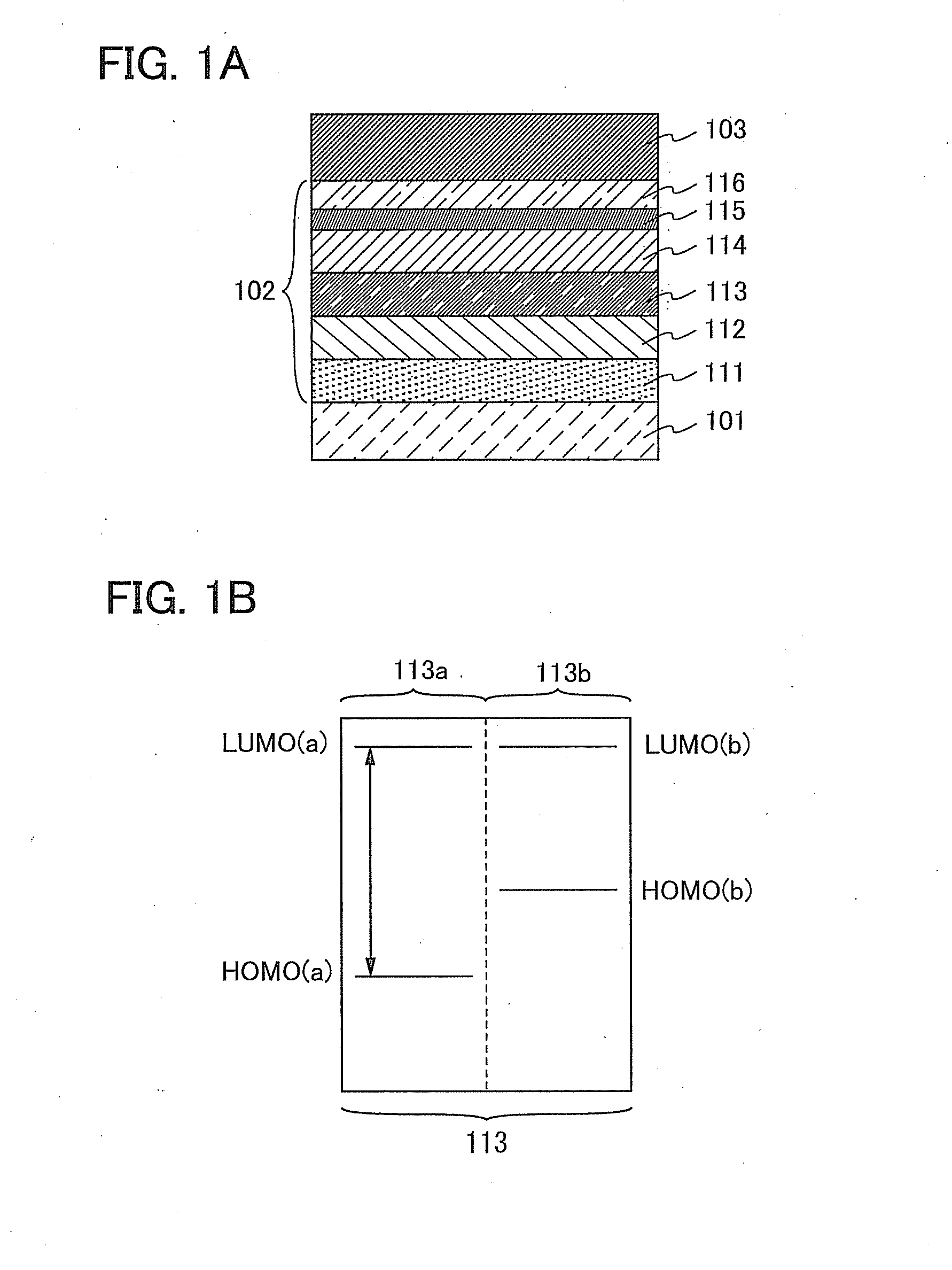
[0052]In this embodiment, a light-emitting element which is one embodiment of the present invention will be described with reference to FIGS. 1A and 1B.

[0053]In the light-emitting element described in this embodiment, as illustrated in FIG. 1A, an EL layer 102 including a light-emitting layer 113 is provided between a pair of electrodes (a first electrode (anode) 101 and a second electrode (cathode) 103), and the EL layer 102 includes a hole-injection layer 111, a hole-transport layer 112, an electron-transport layer 114, an electron-injection layer 115, a charge generation layer (E) 116, and the like in addition to the light-emitting layer 113.

[0054]Application of a voltage to such a light-emitting element causes holes injected from the first electrode 101 side and electrons injected from the second electrode 103 side to recombine in the light-emitting layer 113 and a substance contained in the light-emitting layer 113 to be raised to an excited state. Then, light is emitted when t...

embodiment 2

[0077]In this embodiment, novel pyrene-based compounds which are embodiments of the present invention and can be used in the light-emitting element described in Embodiment 1 will be described.

[0078]One embodiment of the present invention is a pyrene-based compound having a structure represented by the following general formula (G1).

[0079]In the general formula (G1), Ar represents a substituted or unsubstituted aryl group having 6 to 10 carbon atoms, a represents a substituted or unsubstituted phenylene group, and R1 to R12 separately represent a hydrogen atom or an alkyl group having 1 to 4 carbon atoms. Further, R13 to R20 separately represent a hydrogen atom or an alkyl group having 1 to 6 carbon atoms. Further, n is 0 or 1.

[0080]Here, specific examples of a include a phenylene group and a phenylene group substituted by one or more alkyl groups each having 1 to 4 carbon atoms.

[0081]Note that n is preferably equal to 0 in the above general formula (G1) for easier synthesis. Thus, a...

embodiment 3

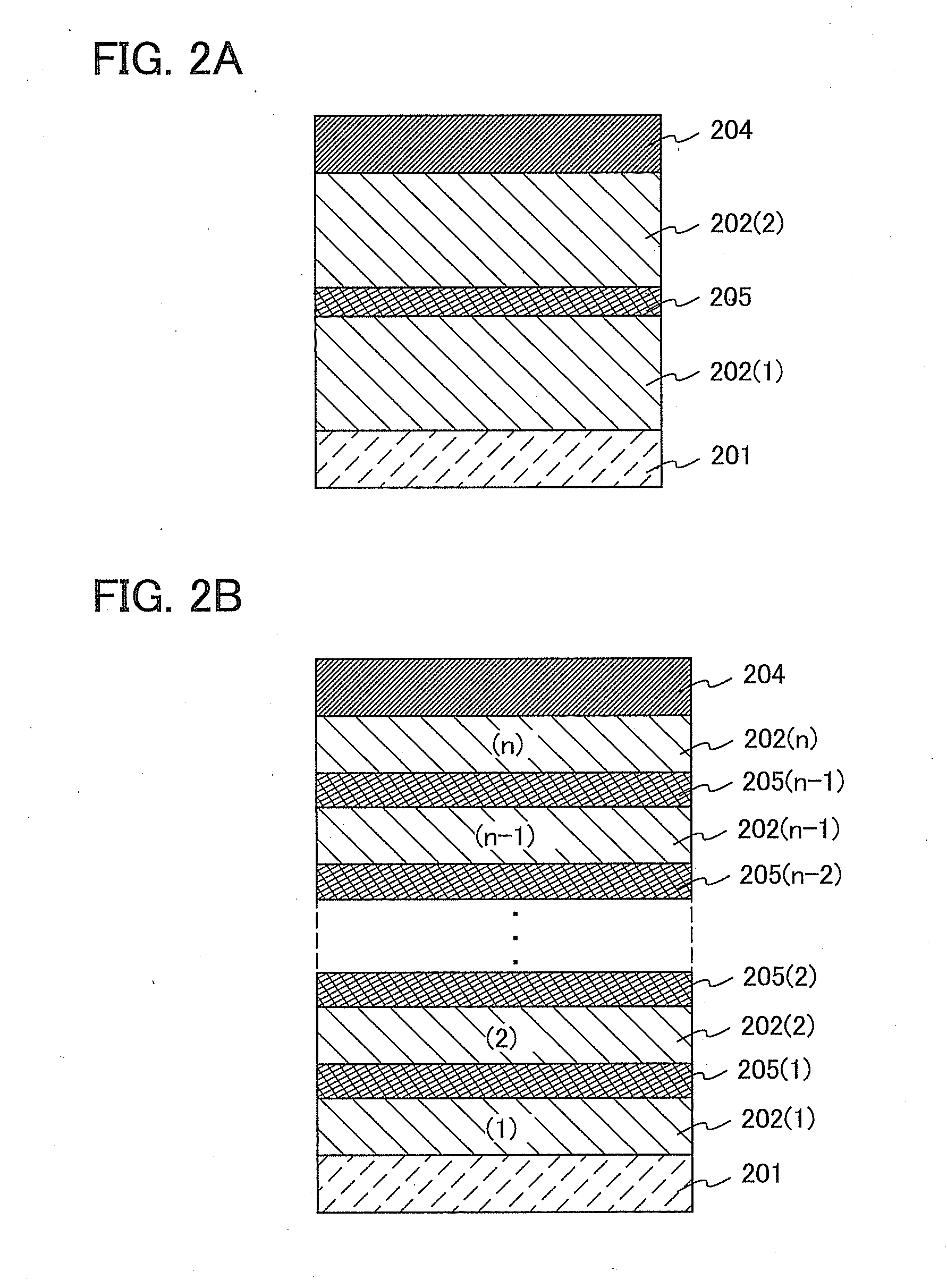
[0104]In this embodiment, as one embodiment of the present invention, a light-emitting element (hereinafter referred to as tandem light-emitting element) in which a charge generation layer is provided between a plurality of EL layers will be described.

[0105]The light-emitting element described in this embodiment is a tandem light-emitting element including a plurality of EL layers (a first EL layer 202(1) and a second EL layer 202(2)) between a pair of electrodes (a first electrode 201 and a second electrode 204) as illustrated in FIG. 2A.

[0106]In this embodiment, the first electrode 201 functions as an anode, and the second electrode 204 functions as a cathode. Note that the first electrode 201 and the second electrode 204 can have structures similar to those described in Embodiment 1. In addition, all or any of the plurality of EL layers (the first EL layer 202(1) and the second EL layer 202(2)) may have structures similar to those described in Embodiment 1. In other words, the st...


PUM

PropertyMeasurementUnit
temperatureaaaaaaaaaa
visible light transmittanceaaaaaaaaaa

Abstract

A highly efficient light-emitting element capable of providing a plurality of emission colors is provided, which does not easily deteriorate and can minimize a decrease in external quantum efficiency even when a light-emitting layer has a stacked structure. A light-emitting device, an electronic device, and a lighting device which have low power consumption and long lifetime are provided. A light-emitting element includes a plurality of light-emitting layers stacked between a pair of electrodes. The light-emitting layers each contain a host material and a guest material. The guest materials of the light-emitting layers are substances which have different HOMO levels but have substantially the same LUMO levels and emit light of different colors. A light-emitting device, an electronic device, and a lighting device are fabricated using the light-emitting element.

Description

BACKGROUND OF THE INVENTION[0001]1. Field of the Invention[0002]One embodiment of the present invention relates to light-emitting elements having a plurality of emission colors. One embodiment of the present invention also relates to light-emitting devices, electronic devices, and lighting devices. One embodiment of the present invention further relates to novel pyrene-based compounds.[0003]2. Description of the Related Art[0004]In recent years, research and development have been extensively conducted on light-emitting elements using electroluminescence (EL). In a basic structure of such a light-emitting element, a layer containing a light-emitting substance is interposed between a pair of electrodes. By applying voltage to this element, light emission from the light-emitting substance can be obtained.[0005]Since such a light-emitting element is of self-light-emitting type, it is considered that the light-emitting element has advantages over a liquid crystal display in that visibili...

Claims


Application Information

Patent Timeline
Patent Type & Authority Applications(United States)
IPC IPC(8): H01L51/54C07D403/12H10K99/00
CPCH01L51/0054H01L51/0059H01L51/0061H01L51/0072H01L51/5278H01L51/5004H01L51/5036H01L51/504C07D209/88C09K11/025C09K11/06Y02B20/00H10K59/32H10K85/622H10K85/631H10K85/636H10K85/6572H10K50/11H10K2101/40H10K50/125H10K50/13H10K50/19H10K50/00H10K85/633H10K85/615H10K2101/30C09K2211/1007C09K2211/1011C09K2211/1014C09K2211/1022C09K2211/1029
Inventor SUZUKI, HIROKISEO, SATOSHIKAWAKAMI, SACHIKOSUZUKI, TSUNENORI
Owner SEMICON ENERGY LAB CO LTD
Learn More