Synchronous machine control apparatus

a control apparatus and synchronous technology, applied in the direction of motor/generator/converter stopper, dynamo-electric gear control, dynamo-electric converter control, etc., can solve the problems of difficult to control the armature voltage to have a desired value, difficult to perform torque control with a high degree of accuracy, and not necessarily desirable control in this manner all the time, etc., to achieve the effect of suppressing loss and heat generation

Inactive Publication Date: 2013-04-11
MITSUBISHI ELECTRIC CORP
View PDF5 Cites 34 Cited by
  • Summary
  • Abstract
  • Description
  • Claims
  • Application Information

AI Technical Summary

Benefits of technology

[0021]The synchronous machine control apparatus configured as above is based on the fact that a suitable operation target varies with conditions of the synchronous machine and the power converter even under the condition that the torque command is the same, and therefore generates an operation target command that suits conditions of the synchronous machine and the power converter and then constantly generates a control command that satisfies an operation target online in consideration of conversion efficiency of the synchronous machine. Hence, there can be achieved an advantage that the synchronous machine can be driven with high efficiency while effectively suppressing a loss and heat generation in the synchronous machine or the power converter.

Problems solved by technology

Meanwhile, in the case of the reluctance motor, it is known that an absolute value of the armature current vector is not proportional to an output torque and it is therefore difficult to perform torque control with a high degree of accuracy by the control method in the related art.
It is therefore difficult to control an armature voltage to have a desired value according to the magnitude of a torque by the control method in the related art.
However, the control in this manner is not necessarily desirable all the time.
It is therefore difficult for the control device of Patent Document 1 to flexibly address these cases.

Method used


Image

  • Synchronous machine control apparatus
  • Synchronous machine control apparatus
  • Synchronous machine control apparatus

Examples


first embodiment

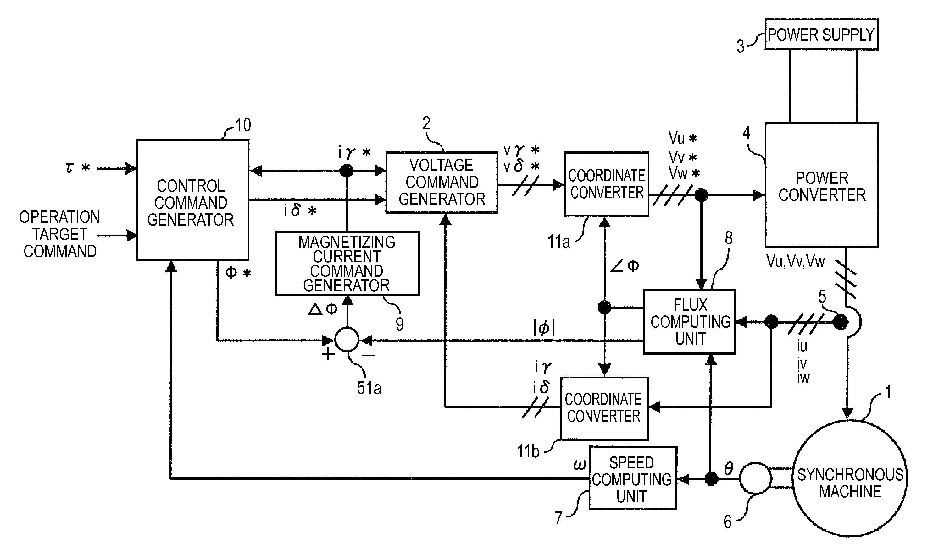
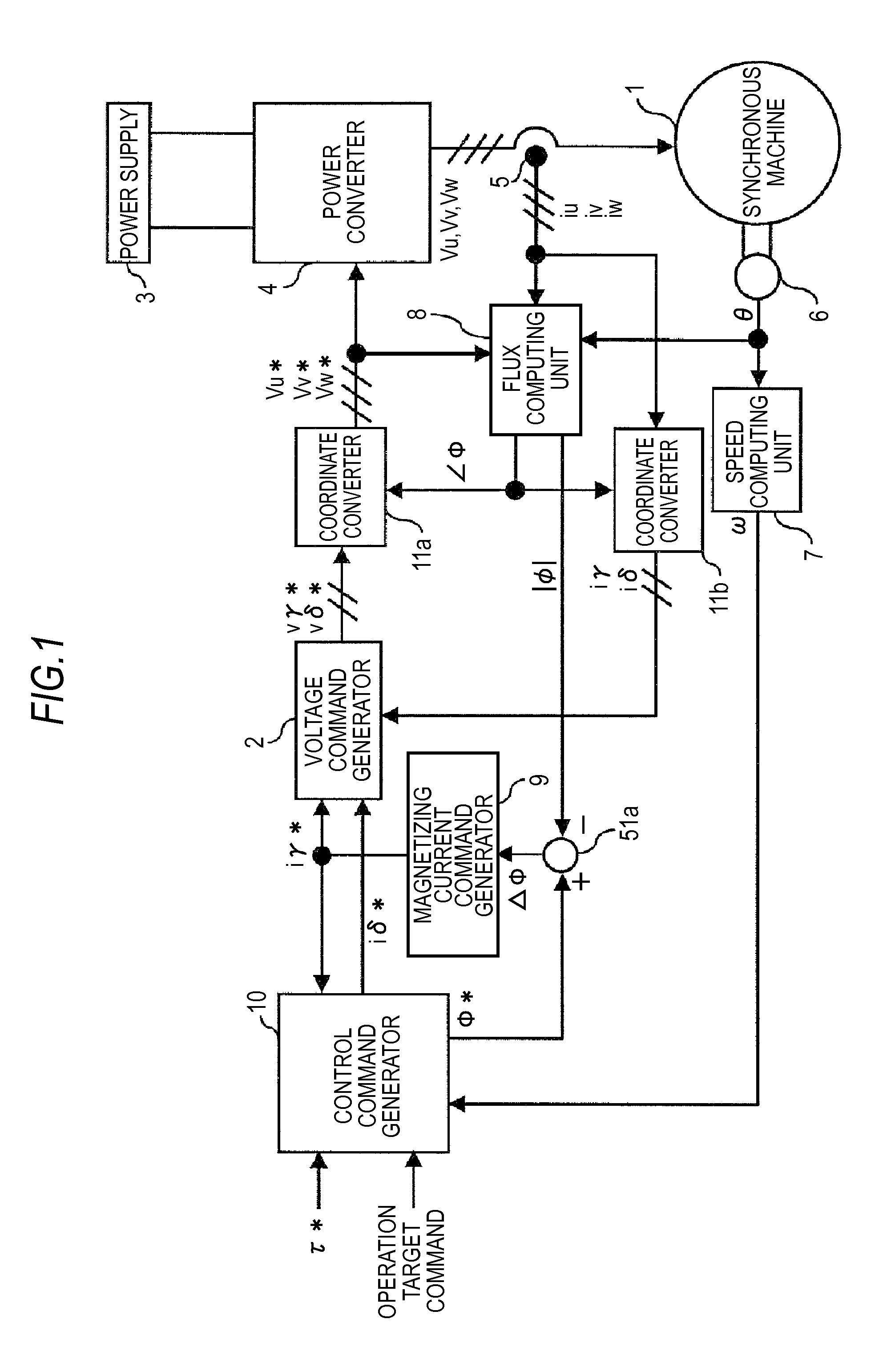
[0047]A synchronous machine control apparatus according to a first embodiment of the invention will be described with reference to FIG. 1. FIG. 1 is a view used to describe the synchronous machine control apparatus of the first embodiment and it is a view showing a synchronous machine control system including a synchronous machine and a synchronous machine control apparatus.

[0048]Hereinafter, descriptions will be given to a configuration of the synchronous machine control apparatus that drives the synchronous machine of the first embodiment and to functions of components. An output end of a power converter that rotary drives the synchronous machine will be described first and then a flow up to generation of a voltage command at an input end of the power converter will be described sequentially.

[0049]The synchronous machine control apparatus that drives the synchronous machine 1 of the first embodiment is configured as follows. That is, a power converter 4 represented by an inverter ...

second embodiment

[0138]A synchronous machine control apparatus according to a second embodiment of the invention will now be described in accordance with FIG. 15. FIG. 15 is a view used to describe the synchronous machine control apparatus of the second embodiment and it shows a synchronous machine control system including a synchronous machine and a synchronous machine control apparatus.

[0139]The synchronous machine control apparatus of the second embodiment is provided with a voltage detector that detects a power supply voltage across the power supply and the control command generator additionally includes a flux command limiter that imposes a limitation on an armature interlinkage flux command on the basis of a rotation speed of the synchronous machine and the power supply voltage.

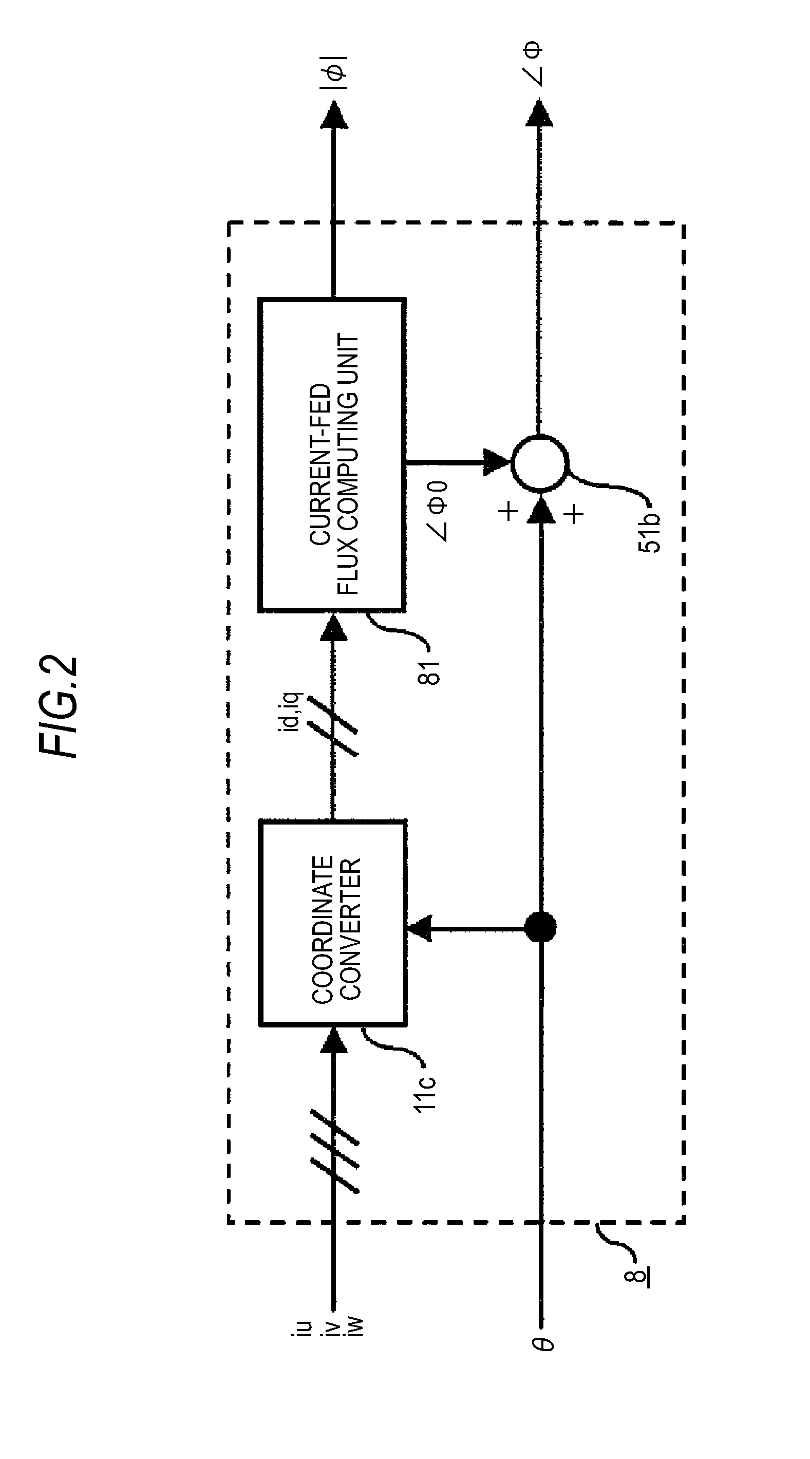
[0140]FIG. 16 is a view showing an example of the configuration of a control command generator 10b formed by adding a flux command limiter 27 to the control command generator 10 (see FIG. 9) described in the first embod...

third embodiment

[0143]A synchronous machine control apparatus according to a third embodiment of the invention will now be described in accordance with FIG. 18. FIG. 18 is a view used to describe the synchronous machine control apparatus of the third embodiment and it shows a synchronous machine control system including a synchronous machine and a synchronous machine control apparatus. Also, FIG. 19 shows another synchronous machine control system according to the third embodiment.

[0144]As are shown in FIG. 18 and FIG. 19, the synchronous machine control apparatus of the third embodiment has a temperature detector 31 or 31a and an operation target command generator 13 or 13a. The operation target command is therefore generated in the operation target command generator 13 or 13a on the basis of the temperature detected by the temperature detector 31 or 31a, respectively. In the drawings of the third embodiment, two components, the voltage detector 12 and the flux command limiter 27, described in the...


PUM


Abstract

A control command generator that generates an armature interlinkage flux command and a torque current command by a torque command, a rotation speed, and an operation target command, includes a first flux command generator generating a first flux command by the toque command or the torque current command, a second flux generator generating a second flux command by the torque command or the torque current command and the rotation speed of the synchronous machine, a command allocation setting unit setting an allocation coefficient equivalent to an allocation ratio of the two first and second flux commands by the operation target command, a flux command adjuster outputting an armature interlinkage flux command by the two flux commands and the allocation coefficient, and a torque current command generator generating the torque current command by the torque command and the armature interlinkage flux command.

Description

BACKGROUND OF THE INVENTION[0001]1. Field of the Invention[0002]The present invention relates to a synchronous machine control apparatus equipped with a power converter that rotary drives a synchronous machine.[0003]2. Description of the Related Art[0004]Synchronous machines include a permanent magnet synchronous motor having a permanent magnet in a rotor and a reluctance motor that generates a torque by utilizing magnetic saliency of a rotor. When such a synchronous machine is controlled by a synchronous machine control apparatus having a power converter, such as an inverter, control widely performed in the related art is to orient an armature current vector in a certain phase direction with respect to the rotor. For example, in the case of a permanent magnet synchronous machine in the related art, an absolute value of an armature current vector is controlled in proportion to a desired torque by controlling the armature current vector to be oriented in a direction orthogonal to a p...

Claims


Application Information

Patent Timeline
Patent Type & Authority Applications(United States)
IPC IPC(8): H02P21/08H02P27/04H02P21/00H02P21/06H02P21/13H02P21/14H02P21/16H02P21/18H02P21/22H02P21/24H02P21/26H02P23/12H02P23/14H02P27/08
CPCH02P21/141H02P21/06
Inventor KOBAYASHI, TAKAHIKOANZAI, KIYOHARUWADA, NORIYUKIMATSUURA, DAIKI
Owner MITSUBISHI ELECTRIC CORP
Why Eureka
Try Eureka